background image

DCM-100 Ethernet Cable Modem 

Installation 

The installation of the DCM-100 Ethernet Cable Modem can be completed in a matter of minutes. Be careful to 

insure the cables are properly locked into position. Follow these steps (see the figure of the rear panel in Chapter 

Two): 

1.  Connect the coaxial TV cable to the DCM-100 jack labeled “CABLE IN.” 

2.  Connect the external power adapter into the connector labeled “POWER” and the other end to the 

electrical outlet. 

3.  Connect one end of the 10BASE-T Ethernet cable (Category 5 or better) to one of your PC’s Ethernet ports 

and the other end into the DCM-200 connector labeled “ETHERNET.”  


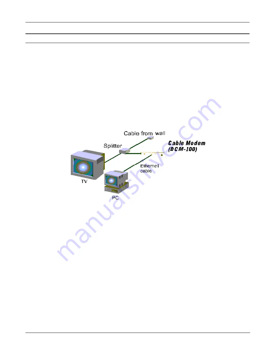
Your setup should look something like this: 


Important Notice: 

♦ 

The DCM-100 Ethernet Cable Modem will work with the Ethernet port connected directly to a PC, hub, 

switch, or a Broadband Router ( i.e. DI-704,DI-713P) 

♦ 

If you shift the Ethernet cable from one PC to another PC, the second PC will not be able to link onto the 

Internet until you reboot the DCM-100 by unplugging the power cord and then reinserting it into the 

DCM-100.  


8


Summary of Contents for DCM-100

Page 1: ...DCM 100 DOCSIS 1 0 Ethernet Cable Modem User s Manual First Edition April 2001 6DCM200 01 Printed in Taiwan RECYCLABLE ...

Page 2: ...Components 4 Front Panel 4 Rear Panel 4 Connection Architecture 5 Understanding Your LED Indicators 6 Powering Up For the First Time 6 Setting Up the Device 7 Before You Start 7 Local Cable Service 7 System Requirements 7 Installation 8 Troubleshooting 9 Contacting Technical Support 10 Offices 11 Specifications 12 LIMITED WARRANTY 14 2 ...

Page 3: ... receive transmissions at up to 42 88 Mbps To give you an idea of just how fast this is digitized television quality video and audio are transmitted together at about 3 Mbps The DCM 100 uses a standard RJ 45 port for a 10BASE T connection to a computer or computer network When properly configured these connections allow simultaneous data transfers to the Internet via the cable company s network Fe...

Page 4: ...he offices listed at the rear of the manual for replacement Identifying External Components This section identifies all the major external components of the device Both the front and rear panels are shown below followed by a description of each panel feature The indicator panel is described in detail in the next chapter Front Panel The figure below shows the front panel of the device DCM 100 LED I...

Page 5: ...cable TV wire the cable TV wall outlet should be connected to a splitter Splitter This unit usually provided by your cable TV company during installation splits the signal onto a second wire The two wires coming out of the splitter can be connected to your TV or set top box and the cable modem NOTE 1 If your cable TV company does not provide a splitter or you chose to buy your own make sure you ge...

Page 6: ...r cable modem port Status This LED is lit green when the Ethernet cable is properly connected to your PC and a traditional coaxial cable is connected to your Cable Modem tuner This indicates a successful connection with CMTS The LED will now start quickly blinking as the DCM 100 attempts to lock a downstream frequency If this is successful the LED will begin to blink slowly This indicates the mode...

Page 7: ...m Requirements The capabilities and limitations of your computer equipment and configuration can affect the overall performance of your Internet connection The DCM 100 Ethernet Cable Modem is designed to work with the following operating systems Windows 98 98 SE Second Edition Windows NT 4 0 Windows 2000 Windows ME Millennium Edition Active Ethernet Port or Nic Installed TCP IP installed on all de...

Page 8: ...er end to the electrical outlet 3 Connect one end of the 10BASE T Ethernet cable Category 5 or better to one of your PC s Ethernet ports and the other end into the DCM 200 connector labeled ETHERNET Your setup should look something like this Important Notice The DCM 100 Ethernet Cable Modem will work with the Ethernet port connected directly to a PC hub switch or a Broadband Router i e DI 704 DI 7...

Page 9: ...tings Check your web browser configuration per ISP instruction Status LED indicator blinks continuously Check the cable line connection If this is secure then there may be a weak signal coming from the central office Report the problem to your cable operator if the cable connection appears to be OK LED indicators appear to be normal but Internet access cannot be established Try to establish a new ...

Page 10: ...t D Link technical support through our web site e mail or by phone United States technical support is available Monday through Friday from 6 00 a m to 6 00 p m PST Web http www dlink com Email support dlink com Phone 949 788 0805 option 4 If you are a customer residing outside of the United States please refer to the list of D Link locations that is included in this manual Thank you for purchasing...

Page 11: ...71199 analog BBS 49 0 6192 971198 ISDN INFO 00800 7250 0000 toll free HELP 00800 7250 4000 toll free REPAIR 00800 7250 8000 E MAIL info dlink de INDIA D Link India Plot No 5 Kurla Bandra Complex Rd Off Cst Rd Santacruz E Bombay 400 098 India TEL 91 22 652 6696 FAX 91 22 652 8914 URL www dlink india com E MAIL service dlink india com ITALY D Link Mediterraneo Srl Via Nino Bonnet n 6 b 20154 Milano ...

Page 12: ...6 MHz Receive Level 15dBmV to 15dBmV Upstream Transmitter Modulation QPSK 16 QAM Data Speed 320K 640K 1280K 2560K 5120Kbps QPSK 640K 1280K 2560K 5120K 10240Kbps 16 QAM Frequency Range 5 MHz to 42 MHz Channel Bandwidth 200K 400K 800K 1 6M 3 2M Hz Transmission Level 8 to 55dBmV 16 QAM 8 to 58dBmV QPSK Error Correction Reed Solomon Interface CPE Interface 10BASE T Ethernet RJ45 RF Interface F Type Fe...

Page 13: ...er Consumption 12W maximum Operating Temperature 32 104 F 0 40 C Operating Humidity 10 90 Storage Temperature 4 140 F 20 60 C Dimensions 22 W x 174 D x 35 H mm Weight 578 grams 1 271b EMI Certification FCC Class B CE Class B C Tick 13 ...

Page 14: ...nt functional specifications for the Software as set forth in the applicable documentation from the date of original delivery of the Software for a period of ninety 90 days Warranty Period if the Software is properly installed on approved hardware and operated as contemplated in its documentation D Link further warrants that during the Warranty Period the magnetic media on which D Link delivers th...

Page 15: ...RRITORY WHERE A PRODUCT IS SOLD THE DURATION OF SUCH IMPLIED WARRANTY SHALL BE LIMITED TO NINETY 90 DAYS EXCEPT AS EXPRESSLY COVERED UNDER THE LIMITED WARRANTY PROVIDED HEREIN THE ENTIRE RISK AS TO THE QUALITY SELECTION AND PERFORMANCE OF THE PRODUCT IS WITH THE PURCHASER OF THE PRODUCT Limitation of Liability TO THE MAXIMUM EXTENT PERMITTED BY LAW D LINK IS NOT LIABLE UNDER ANY CONTRACT NEGLIGENC...

Page 16: ...ate the receiving antenna Increase the separation between the equipment and receiver Connect the equipment into an outlet on a circuit different from that to which the receiver is connected Consult the dealer or an experienced radio TV technician for help CE Mark Warning This is a Class B product In a domestic environment this product may cause radio interference in which case the user may be requ...

Page 17: ...help us to support your product 1 Where and how will the product primarily be used Home Office Travel Company Business Home Business Personal Use 2 How many employees work at installation site 1 employee 2 9 10 49 50 99 100 499 500 999 1000 or more 3 What network protocol s does your organization use XNS IPX TCP IP DECnet Others_____________________________ 4 What network operating system s does y...

Page 18: ...DCM 100 Ethernet Cable Modem 18 ...

Reviews: