background image


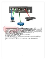
The following figure shows the front panel connection of DAS-3248:


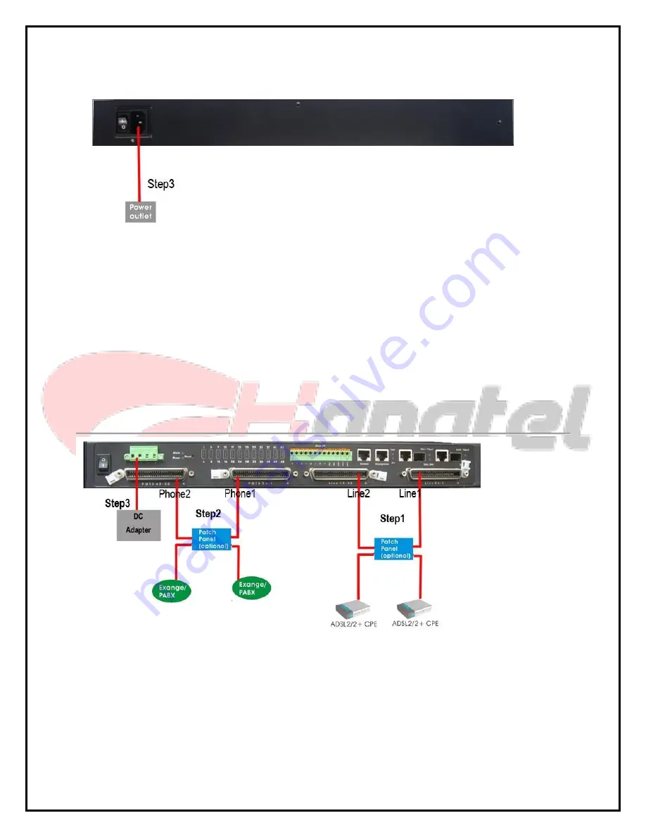
The following figure shows the rear panel connection of DAS-3248:


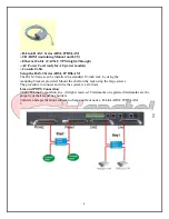
Step 1: Connect the ADSL line connector(s), a 50-pin centronic connector, of DAS- 
3 Series IP DSLAM to CPE’s by using telco cable. Each line connector can  
support up to 24 ports of ADSL/ADSL2/2+ for Data path. 
Step 2: Connect the phone connector(s), a 50-pin centronic connector, of DAS-3  
Series IP DSLAM to Exchange/PBX by using telco cable.  
Step 3: Connect to AC power outlet and turn the power switch to “|”. 
©2007 D-Link Corporation, Inc. All rights reserved. Trademarks or registered trademarks are the 
property of their respective holders.  
Software and specifications subject to change without notice. D-Link ADSL IP DSLAM. 


Summary of Contents for DAS-3 Series

Page 1: ... for the main setup procedure For more detailed information about complete installation and configuration please refer to the User s Manual on master CD included with your DLSAM Check Your Package Contents 2007 D Link Corporation Inc All rights reserved Trademarks or registered trademarks are the property of their respective holders Software and specifications subject to change without notice D Li...

Page 2: ... installed in a standard 19 inch rack by using the mounting brackets provided Mount the shelf on the rack using the large screws The procedure to connect and wire the system is as follows Line and POTS Connection 2007 D Link Corporation Inc All rights reserved Trademarks or registered trademarks are the property of their respective holders Software and specifications subject to change without noti...

Page 3: ...connector can support up to 24 ports of ADSL ADSL2 2 for Data path Step 2 Connect the phone connector s a 50 pin centronic connector of DAS 3 Series IP DSLAM to Exchange PBX by using telco cable Step 3 Connect to AC power outlet and turn the power switch to 2007 D Link Corporation Inc All rights reserved Trademarks or registered trademarks are the property of their respective holders Software and ...

Page 4: ...L2 2 for Data path Step 2 Connect the phone connector s a 50 pin centronic connector of DAS 3248 DC to Exchange PBX by using telco cable Step 3 Connect to DC power and then turn on the DC Power Supply Uplink Downlink and Mgmt Connection 2007 D Link Corporation Inc All rights reserved Trademarks or registered trademarks are the property of their respective holders Software and specifications subjec...

Page 5: ... then click login button to login DAS3 Series Web Management Login Window Even though you can connect to the IP DSLAM Eth1 Fiber1 uplink or Eth2 Fiber2 downlink it is recommended that you connect your computer to management port for initial configuration The DAS3 series web management login User name Password dnld dnld of default value 2007 D Link Corporation Inc All rights reserved Trademarks or ...

Page 6: ...ct to EMS it is necessary that your PC s IP and DAS 3 Series s IP are in the same subnet Note DAS 3 Series s default MGNT IP prefix length is 192 168 1 1 24 2 Create management IP into the DAS 3 Series so that the authorized IP agent can 2007 D Link Corporation Inc All rights reserved Trademarks or registered trademarks are the property of their respective holders Software and specifications subje...

Page 7: ...xxx is the IP of your PC and public is the SNMP community Note To access the CLI Ex mode via a direct VT100 compatible terminal connection to the Console Port use the following procedure DAS 3 Series Console Management Setting Table Parameter Setting Baud rate 9600 Data bits 8 Parity None Start bits 1 Stop bits 1 Flow None control Configure the System Click on the Menu System Information from the ...

Page 8: ...s Software and specifications subject to change without notice D Link ADSL IP DSLAM 7 Open the Deployment from the menu tree The DAS 3 Series Configuration menu and related windows will appear as follows Item Description DSL port The PVC Management dialog has the ability to configure the ATM PVC on ADSL port interface DSL profile ...

Page 9: ...attach the DSL mapping profile to the ADSL line interface PVC setting The PVC Management dialog has the ability to configure the ATM PVC on ADSL port interface DSL port Dialog Select port to be enabled or disabled 2007 D Link Corporation Inc All rights reserved Trademarks or registered trademarks are the property of their respective holders Software and specifications subject to change without not...

Page 10: ...ction parameters Enter the control values to the text box and click Add to activate 2007 D Link Corporation Inc All rights reserved Trademarks or registered trademarks are the property of their respective holders Software and specifications subject to change without notice D Link ADSL IP DSLAM 9 ...

Page 11: ...e 1 Table 1 Default DSL Profile Setting Item Setting Line Interface Standard type ADSL2Plus AnnexM off Line Type interleave Rate Mode adaptAtStartup SNR Margin ATUC ATUR Target SNR Margin db 10 60 Minimum SNR Margin db 10 0 Maximum SNR Margin db 10 310 Tx Rate and Delay ATUC ATUR Minimum Tx Rate Kbps 64 ...

Page 12: ... L3 enable L2 Entry Rate Kbps 256 L2 Minimum Rate Kbps 1024 L2 Entry Time sec 1800 L2 Exit Rate Kbps 512 2007 D Link Corporation Inc All rights reserved Trademarks or registered trademarks are the property of their respective holders Software and specifications subject to change without notice D Link ADSL IP DSLAM 10 ...

Page 13: ...operty of their respective holders Software and specifications subject to change without notice D Link ADSL IP DSLAM 11 Advanced Setting For more detailed information about complete configuration please refer to the User s Manual on master CD 2007 D Link Corporation Inc All rights reserved Trademarks or registered trademarks are the property of their respective holders Software and specifications ...

Page 14: ...14 پ ایان ...
Reviews: