background image

DAP-1620


AC1300 MU-MIMO Wi-Fi Range Extender

User Manual

Installation and Connection

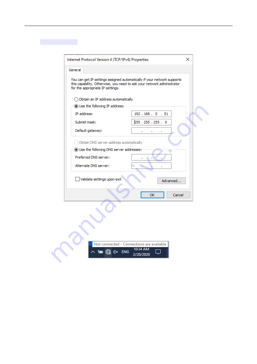
6. Select   the  

Use   the   following   IP   address

  radio   button   and   enter   the   value 

192.168.0.51

  in   the  

IP  address

  field.  The  

Subnet   mask

  field   will   be   filled   in 

automatically. Click the 

OK

 button.

Figure 18. The 

Internet Protocol Version 4 (TCP/IPv4) Properties 

window.

7. Click the 

Close

 button in the connection properties window.

8. To open  the list of available wireless networks, select the icon of the wireless network 

connection   and   click   the  

Connect   To


button   or   left-click   the   network   icon  in   the 

notification area located on the right side of the taskbar.

Figure 19. The notification area of the taskbar.

Page 

30

 of 125

Summary of Contents for DAP-1620

Page 1: ...User Manual DAP 1620 AC1300 MU MIMO Wi Fi Range Extender June 2020 ...

Page 2: ...Wi Fi Adapter 25 Configuring Wi Fi Adapter in OS Windows 7 26 Configuring Wi Fi Adapter in OS Windows 10 29 Connecting to Web based Interface 32 Web based Interface Structure 34 Summary Page 34 Menu Sections 35 Notifications 36 Chapter 4 Configuring via Web based Interface 37 Initial Configuration Wizard 37 Selecting Operation Mode 39 Access Point or Repeater 39 Mesh Network Subordinate Device Sla...

Page 3: ...itional 80 MAC Filter 84 Super Mesh 86 Roaming 91 Advanced 93 DNS 94 Ports Settings 95 MAC Filter 98 System 100 Configuration 101 Firmware Update 103 Local Update 104 Remote Update 105 Schedule 106 Log 110 Ping 112 Traceroute 114 Telnet SSH 116 System Time 117 Auto Provision 119 Chapter 5 Operation Guidelines 121 Safety Rules and Conditions 121 Wireless Installation Considerations 122 Chapter 6 Ab...

Page 4: ...ument Change A name of a menu menu item control field checkbox drop down list button etc 192 168 0 50 Data that you should enter in the specified field Information An important note Document Structure Chapter 1 describes the purpose and structure of the document Chapter 2 gives an overview of the device s hardware and software features describes its appearance and the package contents Chapter 3 ex...

Page 5: ...antennas radiation pattern and to redistribute the signal directly to wireless devices connected to the extender Smart adjustment of Wi Fi clients is useful for networks based on several D Link access points or routers when the smart adjustment function is configured on each of them a client always connects to the access point router extender with the highest signal level The wireless extender is ...

Page 6: ...tainment of LAN IP address DNS relay Autonegotiation of speed duplex mode and flow control Manual speed and duplex mode setup for Ethernet port Firewall functions MAC filter Management and monitoring Access to settings through SSH TELNET WEB HTTP HTTPS Multilingual web based interface for configuration and management Firmware update via web based interface Automatic notification on new firmware ve...

Page 7: ...12 18 24 36 48 and 54Mbps IEEE 802 11n 2 4GHz 6 5 300Mbps MCS0 MCS15 to 400Mbps QAM256 IEEE 802 11n 5GHz from 6 5 to 300Mbps from MCS0 to MCS15 IEEE 802 11ac 5GHz from 6 5 to 867Mbps from MCS0 to MSC9 Transmitter output power The maximum value of the transmitter output power depends upon the radio frequency regulations applied in your country 802 11a typical at room temperature 25 C 12dBm 2 dB 802...

Page 8: ... 82dBm at 36Mbps 77dBm at 48Mbps 76dBm at 54Mbps 802 11n 2 4GHz typical at PER 10 1000 byte PDUs at room temperature 25 C HT20 93dBm at MCS0 8 90dBm at MCS1 9 88dBm at MCS2 10 85dBm at MCS3 11 81dBm at MCS4 12 77dBm at MCS5 13 76dBm at MCS6 14 74dBm at MCS7 15 HT40 91dBm at MCS0 8 88dBm at MCS1 9 85dBm at MCS2 10 82dBm at MCS3 11 79dBm at MCS4 12 75dBm at MCS5 13 73dBm at MCS6 14 72dBm at MCS7 15 ...

Page 9: ...CS0 83dBm at MCS1 80dBm at MCS2 77dBm at MCS3 74dBm at MCS4 70dBm at MCS5 68dBm at MCS6 67dBm at MCS7 63dBm at MCS8 61dBm at MCS9 Modulation schemes 802 11a BPSK QPSK 16QAM 64QAM with OFDM 802 11b DQPSK DBPSK DSSS CCK 802 11g BPSK QPSK 16QAM 64QAM with OFDM 802 11n BPSK QPSK 16QAM 64QAM 256QAM with OFDM 802 11ac BPSK QPSK 16QAM 64QAM up to 256QAM with OFDM Physical Parameters Dimensions 64 x 50 x ...

Page 10: ...he device is being loaded Solid green The device is ready for use Blinking red Attempting to add a wireless device via the WPS function No light The extender is powered off Wi Fi Signal Strength Solid red The device is not connected to a wireless network or the signal strength is poor Solid green Fair signal strength Solid green Good signal strength Page 10 of 125 ...

Page 11: ...rove the signal strength move the extender closer to the source of the signal In case the POWER WPS LED is solid red one of the Wi Fi Signal Strength LEDs is solid red and the other two are blinking green the device is in the emergency mode Restore the factory default settings via the hardware RESET button WPS button is located on the front panel of the extender Button Description WPS A button to ...

Page 12: ...l of the device Name Description LAN An Ethernet port to connect to a computer or a wired router RESET A button to restore the factory default settings To restore the factory defaults push the button with the device turned on hold it for 10 seconds and then release the button The device is also equipped with two external non detachable Wi Fi antennas Page 12 of 125 ...

Page 13: ...ded Extender DAP 1620 Quick Installation Guide brochure The User Manual and Quick Installation Guide documents are available on D Link website see www dlink ru Using a power supply with different parameters than those indicated on the device will cause damage and void the warranty for this product Page 13 of 125 ...

Page 14: ...20 10240 and later Mozilla Firefox 44 and later Opera 35 and later For successful operation JavaScript should be enabled on the web browser Make sure that JavaScript has not been disabled by other software such as virus protection or web user security packages running on your computer Wired or Wireless NIC Ethernet or Wi Fi Adapter Any computer that uses the extender should be equipped with an Eth...

Page 15: ...onnecting to PC PC with Ethernet Adapter 1 Connect an Ethernet cable between the LAN port of the extender and the Ethernet port of your PC 2 Plug the device into an electrical outlet or power strip Now you need to configure an IP address for the Ethernet adapter of your PC Page 15 of 125 ...

Page 16: ...ceed to the Control Panel window 2 Select the Network and Sharing Center section If the Control Panel has the category view the Category value is selected from the View by drop down list in the top right corner of the window choose the View network status and tasks line under the Network and Internet section Figure 3 The Control Panel window Page 16 of 125 ...

Page 17: ...MIMO Wi Fi Range Extender User Manual Installation and Connection 3 In the menu located on the left part of the window select the Change adapter settings line Figure 4 The Network and Sharing Center window Page 17 of 125 ...

Page 18: ...ge Extender User Manual Installation and Connection 4 In the opened window right click the relevant Local Area Connection icon and select the Properties line in the menu displayed Figure 5 The Network Connections window Page 18 of 125 ...

Page 19: ...anual Installation and Connection 5 In the Local Area Connection Properties window on the Networking tab select the Internet Protocol Version 4 TCP IPv4 line Click the Properties button Figure 6 The Local Area Connection Properties window Page 19 of 125 ...

Page 20: ...will be filled in automatically Click the OK button Figure 7 The Internet Protocol Version 4 TCP IPv4 Properties window 7 Click the OK button in the connection properties window Now you can connect to the web based interface of DAP 1620 for configuring all needed parameters To gain access to an external network to the Internet you also need to specify the default gateway and the addresses of DNS s...

Page 21: ...Extender User Manual Installation and Connection Configuring IP Address in OS Windows 10 1 Click the Start button and proceed to the Settings window 2 Select the Network Internet section Figure 8 The Windows Settings window Page 21 of 125 ...

Page 22: ...C1300 MU MIMO Wi Fi Range Extender User Manual Installation and Connection 3 In the Change your network settings section select the Change adapter options line Figure 9 The Network Internet window Page 22 of 125 ...

Page 23: ...al Area Connection icon and select the Properties line in the menu displayed Figure 10 The Network Connections window 5 In the Local Area Connection Properties window on the Networking tab select the Internet Protocol Version 4 TCP IPv4 line Click the Properties button Figure 11 The local area connection properties window Page 23 of 125 ...

Page 24: ...ll be filled in automatically Click the OK button Figure 12 The Internet Protocol Version 4 TCP IPv4 Properties window 7 Click the Close button in the connection properties window Now you can connect to the web based interface of DAP 1620 for configuring all needed parameters To gain access to an external network to the Internet you also need to specify the default gateway and the addresses of DNS...

Page 25: ...ke sure that the Wi Fi adapter of your PC is on As a rule modern notebooks with built in wireless NICs are equipped with a button or switch that turns on off the wireless adapter refer to your PC documents If your PC is equipped with a pluggable wireless NIC install the software provided with your Wi Fi adapter Now you should configure your Wi Fi adapter Page 25 of 125 ...

Page 26: ...f the window choose the View network status and tasks line under the Network and Internet section Figure 13 The Control Panel window 3 In the menu located on the left part of the window select the Change adapter settings line 4 In the opened window right click the relevant Wireless Network Connection icon Make sure that your Wi Fi adapter is on then select the Properties line in the menu displayed...

Page 27: ...ically Click the OK button Figure 14 The Internet Protocol Version 4 TCP IPv4 Properties window 7 Click the OK button in the connection properties window 8 To open the list of available wireless networks select the icon of the wireless network connection and click the Connect To button or left click the network icon in the notification area located on the right side of the taskbar Figure 15 The no...

Page 28: ...s After the connection is established the network icon will be displayed as the signal level scale Now you can connect to the web based interface of DAP 1620 for configuring all needed parameters To gain access to an external network to the Internet you also need to specify the default gateway and the addresses of DNS servers If you perform initial configuration of the extender via Wi Fi connectio...

Page 29: ... Settings window 3 In the Change your network settings section select the Change adapter options line 4 In the opened window right click the relevant Wireless Network Connection icon Make sure that your Wi Fi adapter is on then select the Properties line in the menu displayed 5 In the Wireless Network Connection Properties window on the Networking tab select the Internet Protocol Version 4 TCP IPv...

Page 30: ...cally Click the OK button Figure 18 The Internet Protocol Version 4 TCP IPv4 Properties window 7 Click the Close button in the connection properties window 8 To open the list of available wireless networks select the icon of the wireless network connection and click the Connect To button or left click the network icon in the notification area located on the right side of the taskbar Figure 19 The ...

Page 31: ...ettings 12 Wait for about 20 30 seconds After the connection is established the network icon will be displayed as a dot with curved lines indicating the signal level Now you can connect to the web based interface of DAP 1620 for configuring all needed parameters To gain access to an external network to the Internet you also need to specify the default gateway and the addresses of DNS servers If yo...

Page 32: ...the following IP address is specified 192 168 0 50 Press the Enter key Figure 22 Connecting to the web based interface of the DAP 1620 device If the error The page cannot be displayed or Unable to display the page Could not connect to remote server occurs upon connecting to the web based interface of the extender make sure that you have properly connected the extender to your computer If the devic...

Page 33: ...word you specified in the Password field then click the LOGIN button Figure 24 The login page In order not to log out move the Stay signed in switch to the right After closing the web browser or rebooting the device you need to enter the username and the password again If you enter a wrong password several times the web based interface will be blocked for a while Please wait for one minute and ree...

Page 34: ...licking the line the e mail client window for sending a new letter to the specified address opens The Wi Fi 2 4 GHz and Wi Fi 5 GHz sections display data on the state of the device s wireless network its name and the authentication type and availability of an additional wireless network in the relevant band In the LAN section the IPv4 and IPv6 address of the extender the LAN MAC address and the nu...

Page 35: ...tics section page 47 The page of the Connections Setup section is designed for configuring basic parameters of the LAN interface of the extender for the description of the pages see the Connections Setup section page 52 The pages of the Wi Fi section are designed for specifying all needed settings of the extender s wireless network for the description of the pages see the Wi Fi section page 61 The...

Page 36: ...ion Notifications The extender s web based interface displays notifications in the top right part of the page Figure 26 The web based interface notifications Click the icon displaying the number of notifications to view the complete list and click the relevant button Page 36 of 125 ...

Page 37: ...he OK button and wait until the factory default settings are restored Figure 27 Restoring the default settings in the Wizard If you perform initial configuration of the extender via Wi Fi connection please make sure that you are connected to the wireless network of DAP 1620 see the WLAN name SSID on the back panel of the device and click the NEXT button Figure 28 Checking connection to the wireles...

Page 38: ...d interface To do this click the ADVANCED SETTINGS button On the opened page change the default settings specify the user s interface password in the User s interface password and Password confirmation fields and the name of the wireless network in the 2 4GHz and 5GHz bands in the Network name 2 4 GHz SSID and Network name 5 GHz SSID fields correspondingly Then click the APPLY button Figure 31 Cha...

Page 39: ... wireless network to the existing local network on the Device mode page from the Connection method list select the Autonomous value Then from the Work mode list select the Access point value In this mode you can change the LAN IP address set your own settings for the wireless network in the 2 4GHz and 5GHz bands and set your own password for access to the web based interface of the device Figure 3...

Page 40: ...rom the Connection method list select the Autonomous value Then from the Work mode list select the Repeater value In this mode you can change the LAN IP address connect your device to another access point set your own settings for the wireless network in the 2 4GHz and 5GHz bands and set your own password for access to the web based interface of the device Figure 33 Selecting an operation mode The...

Page 41: ...e Role list select the Slave value From the Frequency band list select the band where your main device in the Master role operates Then a device in the Slave role is configured in the assess point mode In this mode you can change the LAN IP address set your own settings for the wireless network in the 2 4GHz and 5GHz bands and set your own password for access to the web based interface of the devi...

Page 42: ...nment of IPv4 address checkbox and fill in the IP address Subnet mask DNS IP address Hostname fields and if needed the Gateway IP address field Make sure that the assigned address does not coincide with the LAN IPv4 address of the router to which your device connects If the LAN IPv4 address of DAP 1620 was changed it may be necessary to change your PC s NIС settings Figure 35 The page for changing...

Page 43: ...assword Figure 36 The page for configuring the Wi Fi client If you connect to a hidden network select the band where the hidden network operates from the Frequency band list and enter the network name in the Network name SSID field Then select a needed value from the Network authentication list and then if needed enter the password in the relevant field When the Open authentication type is selecte...

Page 44: ...key ID drop down list It is required to specify all the fields Click the Show icon to display the entered key When the WPA PSK WPA2 PSK or WPA PSK WPA2 PSK mixed authentication type is selected the following fields are displayed Parameter Description Password PSK A password for WPA encryption Click the Show icon to display the entered password Encryption type An encryption method TKIP AES or TKIP ...

Page 45: ...device 3 If the extender is used as a Wi Fi client you can specify the same parameters of the wireless network as specified for the network to which you are connecting To do this click the USE button available for the Repeater mode 4 You can restore the parameters of the wireless network specified before resetting to factory defaults To do this click the RESTORE button Figure 37 The page for confi...

Page 46: ...new user s interface password In case of losing the new password you can access the settings of the extender only after restoring the factory default settings via the hardware RESET button This procedure wipes out all settings that you have configured for your extender Click the NEXT button to continue or click the BACK button to return to the previous page On the next page check all specified set...

Page 47: ...k Statistics On the Statistics Network Statistics page you can view statistics for all connections existing in the system LAN WLAN For each connection the following data are displayed name and state when the connection is on its name is highlighted in green when the connection is off its name is highlighted in red IP address and subnet mask gateway if the connection is established and volume of da...

Page 48: ...DHCP The Statistics DHCP page displays the information on computers that have been identified by hostnames and MAC addresses and have got IP addresses from the DHCP server of the device as well as the IP address expiration periods the lease time Figure 40 The Statistics DHCP page Page 48 of 125 ...

Page 49: ...41 The Statistics Clients and Session page For each device the following data are displayed the IP address the MAC address and the network interface to which the device is connected To view the information on current sessions of a device select this device in the table On the opened page the following data for each session of the selected device will be displayed the protocol for network packet tr...

Page 50: ... Port Statistics page you can view statistics for traffic passing through the port of the extender The information shown on the page can be used for diagnosing connection problems Figure 42 The Statistics Port Statistics page To view the full list of counters for the port click the line corresponding to the port Page 50 of 125 ...

Page 51: ...s The Statistics Multicast Groups page displays addresses of active multicast groups including IPTV channels and groups for transferring service information to which the device is subscribed and the interface through which the device is subscribed Figure 43 The Statistics Multicast Groups page Page 51 of 125 ...

Page 52: ...44 Configuring the local interface The IPv4 tab The Local IP Address section Parameter Description Local IP Address Mode of local IP address assignment Select the needed value from the drop down list Static The IPv4 address subnet mask and the gateway IP address are assigned manually Dynamic The extender automatically obtains these parameters from the LAN DHCP server or from the router to which it...

Page 53: ...face Parameter Description Gateway IP address The gateway IPv4 address which is used by the extender to connect to the Internet e g for synchronizing the system time with an NTP server Optional Hostname The name of the device assigned to its IPv4 address in the local subnet Page 53 of 125 ...

Page 54: ...When this value is selected the Start IP End IP Lease time fields and the DNS relay and ARP Proxy switches are displayed on the tab Also when this value is selected the DHCP Options and Static IP Addresses sections are displayed on the tab Start IP The start IP address of the address range used by the DHCP server to distribute IP addresses to clients End IP The end IP address of the address range ...

Page 55: ...the devices connected to the extender obtain the address transmitted by the ISP or specified on the Advanced DNS page as the DNS server address ARP Proxy Move the switch to the right so that the extender uses its own MAC address to respond to ARP requests sent to devices in its LAN Move the switch to the left so that the extender uses MAC addresses of devices in its LAN to respond to ARP requests ...

Page 56: ...llowing parameters Parameter Description Known DHCP options From the drop down list select an option which you want to configure Options value Specify the value for the selected option Force Move the switch to the right to let the DHCP server send the selected option regardless of the client s request Move the switch to the left to let the DHCP server send the selected option only when the client ...

Page 57: ...is select the relevant MAC address from the drop down list the field will be filled in automatically Then in the IP address field enter an IPv4 address which will be assigned to the device with the specified MAC address In the Hostname field specify a network name of the device for easier identification optional Click the APPLY button To create MAC IPv4 pairs for the devices connected to the exten...

Page 58: ...ble Figure 50 Configuring the local interface The IPv6 tab The window for changing an IPv6 address In the opened window you can specify the following parameters Parameter Description Local IPv6 Address IPv6 address The IPv6 address of the extender in the local subnet By default the following value is specified fd00 1 Prefix The length of the prefix subnet By default the value 64 is specified Gatew...

Page 59: ... allocates addresses from the range specified in the Address range fields Also when this value is selected the Static IP Addresses section is displayed on the tab Stateless Clients themselves configure IPv6 addresses using the prefix Address range The start and the end values for the latest hextet 16 bit of the range of IPv6 addresses which the DHCPv6 server distributes to clients Lease time The l...

Page 60: ...he relevant MAC address from the drop down list the field will be filled in automatically Then in the IP address field enter an IPv6 address which will be assigned to the device with the specified MAC address In the Hostname field specify a network name of the device for easier identification optional Click the APPLY button To create MAC IPv6 pairs for the devices connected to the extender at the ...

Page 61: ...or your wireless network Basic Settings In the Wi Fi Basic Settings section you can change basic parameters for the wireless interface of the extender and configure the basic and additional wireless networks To configure the 2 4GHz band or 5GHz band go to the relevant tab Figure 53 Basic settings of the wireless LAN in the 2 4GHz band Page 61 of 125 ...

Page 62: ...pened window change the parameters and click the SAVE button or click the DELETE FROM SCHEDULE button Country The country you are in Select a value from the drop down list Wireless mode Operating mode of the wireless network of the extender This parameter defines standards of the devices that will be able to use your wireless network Select a value from the drop down list Select channel automatica...

Page 63: ...vant parameters Figure 54 Creating a wireless network Parameter Description Wi Fi Network Network name SSID A name for the wireless network The name can consist of digits and Latin characters Hide SSID If the switch is moved to the right other users cannot see your Wi Fi network It is recommended not to hide the network in order to simplify initial configuration of the wireless network BSSID The u...

Page 64: ...Existing schedules are displayed in the Interval of execution drop down list in the simplified mode To enable broadcasting at the time specified in the schedule and disable it at the other time select the Enable wireless network broadcasting value from the Action drop down list and click the SAVE button When the wireless connection is disabled the device will not be able to enable broadcasting of ...

Page 65: ...ryption This authentication type is not available when a mode supporting 802 11n or 802 11ac devices is selected from the Wireless mode drop down list on the Wi Fi Basic Settings page WPA WPA based authentication using a RADIUS server WPA PSK WPA based authentication using a PSK WPA2 WPA2 based authentication using a RADIUS server WPA2 PSK WPA2 based authentication using a PSK WPA WPA2 mixed A mix...

Page 66: ...ion type only To activate WEP encryption move the switch to the right Upon that the Default key ID drop down list the Encryption key WEP as HEX switch and four Encryption key fields are displayed on the page Default key ID The number of the key from first to fourth which will be used for WEP encryption Encryption key WEP as HEX Move the switch to the right to set a hexadecimal number as a key for ...

Page 67: ...cription Password PSK A password for WPA encryption The password can contain digits Latin letters uppercase and or lowercase and other characters available in the US keyboard layout 7 Click the Show icon to display the entered password Encryption type An encryption method TKIP AES or TKIP AES Group key update interval The time period in seconds at the end of which a new key for WPA encryption is g...

Page 68: ...he password which the extender uses for communication with the RADIUS server the value of this parameter is specified in the RADIUS server settings Encryption type An encryption method TKIP AES or TKIP AES Group key update interval The time period in seconds at the end of which a new key for WPA encryption is generated When the value 0 is specified for this field the key is not renewed When you ha...

Page 69: ...e 59 The page for managing the wireless clients If you want to disconnect a wireless device from your WLAN select the checkbox in the line containing the MAC address of this device and click the DISCONNECT button To view the latest data on the devices connected to the WLAN click the REFRESH button To view the latest data on a connected device left click the line containing the MAC address of this ...

Page 70: ...upport the WPS function The WPS function allows adding devices only to the basic wireless network of the extender Before using the function you need to configure one of the following authentication types Open with no encryption WPA2 PSK or WPA PSK WPA2 PSK mixed with the AES encryption method When other security settings are specified controls of the WPS page on the tab of the relevant band are no...

Page 71: ...cryption key will be configured automatically the network authentication type will be changed to WPA2 PSK Default PIN code The PIN code of the extender This parameter is used when connecting the extender to a registrar to set the parameters of the WPS function Network name SSID The name of the extender s wireless network Network authentication The network authentication type specified for the wire...

Page 72: ...N 6 Right after that enter the PIN code specified on the cover of the wireless device or in its software in the PIN code field 7 Click the CONNECT button in the web based interface of the extender To connect to the basic wireless network via the PBC method of the WPS function follow the next steps 1 Click the ENABLE WPS button 2 In the WPS Control section click the ESTABLISH CONNECTION button 3 In...

Page 73: ...the settings and close the web based interface click the SAVE button in the notification and then click the Logout line of the menu Later you will be able to add wireless devices to the WLAN by pressing the WPS button of the extender 1 Select the PBC method in the software of the wireless device that you want to connect to the extender s WLAN 2 Click the relevant button in the software or press th...

Page 74: ...eeded action from the drop down list in the Work mode section to configure the WMM function Auto the settings of the WMM function are configured automatically the value is specified by default Manual the settings of the WMM function are configured manually When this value is selected the Access Point and Station sections are displayed on the page Figure 61 The page for configuring the WMM function...

Page 75: ... the relevant line In the opened window change the needed parameters Figure 62 The window for changing parameters of the WMM function Parameter Description AIFSN Arbitrary Inter Frame Space Number This parameter influences time delays for the relevant Access Category The lower the value the higher is the Access Category priority CWMin CWMax Contention Window Minimum Contention Window Maximum Both ...

Page 76: ...ch is moved to the right the device cannot use the relevant Access Category ACK Acknowledgment Answering response requests while transmitting Displayed only in the Access Point section If the switch is moved to the left the extender answers requests If the switch is moved to the right the extender does not answer requests Click the SAVE button Page 76 of 125 ...

Page 77: ...e for configuring the client mode To configure the extender as a client move the Enable switch to the right Upon that the following fields are displayed on the page Parameter Description Broadcast wireless network 2 4 GHz Broadcast wireless network 5 GHz If the switch is moved to the left devices cannot connect to the extender s WLAN Upon that the extender can connect to another access point as a ...

Page 78: ... If needed fill in the BSSID field Then select the needed type of authentication from the Network authentication drop down list When the Open or WEP authentication type is selected the following settings are displayed on the page Parameter Description Enable encryption WEP For Open authentication type only To activate WEP encryption move the switch to the right Upon that the Default key ID drop do...

Page 79: ...ion Click the Show icon to display the entered key Encryption type An encryption method TKIP AES or TKIP AES When you have configured the parameters click the APPLY button When connecting to a wireless access point the wireless channel of DAP 1620 will switch to the channel of the access point to which you have connected In addition the Connection Information section in which you can view the conn...

Page 80: ...l On page of the Wi Fi Additional section you can define additional parameters for the WLAN of the extender To configure the 2 4GHz band or 5GHz band go to the relevant tab Changing parameters presented on this page may negatively affect your WLAN Figure 64 Additional settings of the WLAN Page 80 of 125 ...

Page 81: ...he switch to the right to let the extender automatically choose the channel bandwidth 20MHz or 40MHz depending on availability of other APs within its operational range this setting can substantially lower the data transfer rate of your wireless network The switch is displayed when the 20 40 MHz value is selected from the Bandwidth drop down list TX power The transmit power in percentage terms of ...

Page 82: ...twork this value is recommended if your wireless local area network consists of both 802 11b and 802 11g devices Always On The protection function is always enabled this setting can substantially lower the efficiency of your wireless network Always Off The protection function is always disabled Short GI Guard interval in nanoseconds This parameter defines the interval between symbols transmitted w...

Page 83: ...based Interface Parameter Description Station Keep Alive The time interval in seconds between keep alive checks of wireless devices from your WLAN When the value 0 is specified the checking is disabled When you have configured the parameters click the APPLY button Page 83 of 125 ...

Page 84: ...d to access the WLAN It is recommended to configure the Wi Fi MAC filter through a wired connection to DAP 1620 Figure 65 The page for configuring the MAC filter for the wireless network By default the Wi Fi MAC filter is disabled To configure the MAC filter first you need to create rules specify MAC addresses of devices for which the specified filtering modes will be applied To do this click the ...

Page 85: ...es in the section corresponding to the band 2 4 GHz or 5 GHz left click the line of the wireless network In the opened window move the Enable MAC filter switch to the right Upon that the MAC filter restrict mode drop down list will be displayed Select the Allow value from the drop down list and click the SAVE button To close the wireless network for the devices which MAC addresses are specified on...

Page 86: ...device the Master role and subordinate devices the Slave role Devices connect to each other via wireless or wired connection Settings are transmitted from the main device to a subordinate one at the final step of configuring the Super Mesh function while the devices are connected via an Ethernet cable you don t need to manually specify all the parameters on subordinate devices Figure 67 A Mesh net...

Page 87: ...ue should be the same for all devices of your Mesh network IPv6 If you need to use IPv6 for configuring the Mesh network move the IPv6 switch to the right Enable gateway Move the switch to the right to allow devices of the Mesh network to use this device for connecting to the Internet It is recommended to move the switch to the left when configuring a subordinate device Network name SSID A name of...

Page 88: ... workplace To view data on the current state of your Mesh network select the needed value from the Statistics drop down list List of APs When this value is selected information on all devices of your Mesh network is displayed on the page List of Clients When this value is selected information on all clients connected to the devices of your Mesh network is displayed on the page Neighbours When this...

Page 89: ...s field Neighbour MAC Address The MAC address of the device connected to a Mesh network node The MAC address of this node is displayed in the MAC field Role The short name for the Mesh network device which MAC address is displayed in the Neighbour MAC Address field MASTERAP Master Access Point The main device which provides connection to the Internet RAP Router Access Point A subordinate device co...

Page 90: ...ediate nodes is 0 Rate at path to upper level host The maximum allowed value of connection speed from the device which MAC address is displayed in the Neighbour MAC Address field to the device which MAC address is displayed in the MAC field Host capacity The capacity of the device which MAC address is displayed in the MAC field To view detailed data on a device click the line corresponding to this...

Page 91: ...s points or routers If the function is enabled for all access points routers which establish a wireless network then wireless clients will always connect to the device with the highest signal level Figure 69 The Wi Fi Roaming page To enable the function click the ENABLE button Upon that the following settings are available on the page Parameter Description Port The number of the port used for data...

Page 92: ...oint stores data on the signal strength of the client located on its coverage area Minimum level of connection quality The signal strength upon which the extender access point starts scanning other devices in order to find a device with a higher signal level Dead zone This parameter is used for calculation of the signal strength upon which the smart adjustment function goes off If the signal stren...

Page 93: ...ing via Web based Interface Advanced In this menu you can configure advanced settings of the extender add name servers configure autonegotiation or manually configure speed and duplex mode for the Ethernet port of the extender configure the MAC filter Page 93 of 125 ...

Page 94: ...S servers manually on this page or configure the extender to obtain DNS servers addresses automatically from your ISP upon installing a connection When you use the built in DHCP server the network parameters including DNS servers are distributed to clients automatically Specify needed settings for IPv4 in the Name Servers IPv4 section and for IPv6 in the Name Servers IPv6 section To remove a DNS s...

Page 95: ...ol in the autonegotiation mode This function is used for equal load balancing in ISPs networks Contact your ISP to clarify if this function needs to be enabled Figure 71 The Advanced Ports Settings page In order to configure autonegotiation or configure speed and duplex mode manually for the Ethernet port select it in the table Autonegotiation should be enabled for both devices connected to each o...

Page 96: ...ull value to manually configure speed and duplex mode for the port 10M Half Data transfer in just one direction at a time data can be either sent or received at the maximum possible rate of up to 10Mbps 10M Full Data transfer in two directions simultaneously data can be sent and received at the same time at the maximum possible rate of up to 10Mbps 100M Half Data transfer in just one direction at ...

Page 97: ...ymmetric flow control Move the switch to the right to enable the flow control function for the port Move the switch to the left to disable the flow control function for the port After specifying the needed parameters click the SAVE button If in the future you need to edit the parameters of the extender s port select the port in the table In the opened window change the needed parameters and click ...

Page 98: ...igure filtering for all devices of the extender s network Allow Allows access to the extender s network and to the Internet for devices the value is specified by default Deny Blocks access to the extender s network for devices You can use the Deny mode only if an active rule which allows access to the device s network is created on the page To create a rule specify a MAC address of a device for wh...

Page 99: ...r the device with the specified MAC address even if the default mode denies access for all devices MAC address The MAC address of a device from the extender s LAN You can enter the MAC address of a device connected to the extender s LAN at the moment To do this select the relevant device from the drop down list the field will be filled in automatically After specifying the needed parameters click ...

Page 100: ...ce language update the firmware of the extender configure automatic notification on new firmware version enable disable Wi Fi connection and configure automatic reboot of the device on a schedule and set a schedule for different filter rules view the system log configure sending the system log to a remote host check availability of a host on the Internet through the web based interface of the exte...

Page 101: ...n order to change the password for the administrator account in the User section enter a new password in the New password and Password confirmation fields Use digits Latin letters uppercase and or lowercase and other characters available in the US keyboard layout 11 Click the Show icon to display the entered values Then click the SAVE button Remember or write down the new password for the administ...

Page 102: ...r Restore Click the button and follow the dialog box appeared to select a previously saved configuration file all settings of the extender located on your PC and upload it Save Click the button to save settings to the non volatile memory The extender saves changed settings automatically If changed settings have not been saved automatically a notification is displayed in the top right part of the p...

Page 103: ...ck If a firmware update is available a notification will be displayed in the top right corner of the page To disable the automatic check for firmware updates in the Remote Update section move the Check for updates automatically switch to the left and click the APPLY SETTINGS button To enable the automatic check for firmware updates in the Remote Update section move the Check for updates automatica...

Page 104: ...date page to locate the new firmware file 3 If you want to restore the factory default settings immediately after updating the firmware move the Restore factory defaults after firmware update switch to the right 4 Click the UPDATE FIRMWARE button 5 Wait until the extender is rebooted about one and a half or two minutes 6 Log into the web based interface using the login admin and the current passwo...

Page 105: ...he CHECK FOR UPDATES button to check if a newer firmware version exists 2 Click the UPDATE FIRMWARE button the button is displayed if a newer version of the firmware is available 3 Wait until the extender is rebooted about one and a half or two minutes 4 Log into the web based interface using the login admin and the current password If after updating the firmware the extender doesn t work correctl...

Page 106: ...schedule for different filter rules Before creating a schedule you need to configure automatic synchronization of the system time with a time server on the Internet see the System Time section page 117 Figure 77 The System Schedule page To configure automatic reboot of the device on a schedule click the REBOOT ON SCHEDULE button in the Auto Reboot section Figure 78 The window for configuring autom...

Page 107: ...he device will be automatically rebooted To do this select the checkbox located to the left of the relevant value Day of month Specify a day of the month You can specify one value or several values separated by a comma In the advanced mode you can specify more parameters for the schedule using a cron expression To do this select the Advanced mode choice of the radio button and specify the needed v...

Page 108: ...e All Tasks section Figure 79 The window for adding a schedule for a task In the opened window in the System Time field the system time of the device is displayed You can select the Simplified mode choice of the radio button and specify the following parameters Parameter Description Perform task on schedule Move the switch to the right to enable the schedule Move the switch to the left to disable ...

Page 109: ...levant value Day of month Specify a day of the month You can specify one value or several values separated by a comma In the advanced mode you can specify more parameters for the schedule using a cron expression To do this select the Advanced mode choice of the radio button and specify the needed values in the fields displayed You can specify one value or several values separated by a comma You ca...

Page 110: ...eter Description Type Select a type of logging from the drop down list Local the system log is stored in the extender s memory When this value is selected the Server and Port fields are not displayed Remote the system log is sent to the remote host specified in the Server field Remote and local the system log is stored in the extender s memory and sent to the remote host specified in the Server fi...

Page 111: ...e needed parameters click the APPLY button To disable logging of the system events move the Enable switch to the left and click the APPLY button To view the system log go to the Log tab Figure 81 The System Log page The Log tab To view the latest system events click the REFRESH button To save the system log to your PC click the EXPORT button The file will be stored in the download location of your...

Page 112: ...s to a specified host and receives echo replies Figure 82 The System Ping page To check availability of a host enter the IP address or name of this host in the Host field and specify a number of requests that will be sent in order to check its availability in the Count of packets field If availability check should be performed with IPv6 move the IPv6 switch to the right To specify additional setti...

Page 113: ...se field specify the response waiting period in seconds To restore the default field values click the DEFAULT SETTINGS button After specifying the additional parameters click the OK button To run the check click the START button After a while the results will be displayed on the page If you need to interrupt the check click the CANCEL button the button is available from the moment the check starts...

Page 114: ...stem Traceroute page you can determine the route of data transfer to a host via the traceroute utility Figure 84 The System Traceroute page To determine the route enter the name or IP address of a host in the Host field If the route should be determined using IPv6 move the IPv6 switch to the right Page 114 of 125 ...

Page 115: ...default value is 30 Number of probes The number of attempts to hit an intermediate host Wait time A period of waiting for an intermediate host response To restore the default field values click the DEFAULT SETTINGS button After specifying the additional parameters click the OK button To run the check click the START button After a while the results will be displayed on the page If you need to inte...

Page 116: ...net SSH page To enable access via TELNET and or SSH move the Enable Telnet switch and or Enable SSH switch to the right In the Port field enter the number of the extender s port through which access will be allowed by default the port 23 is specified for Telnet and the port 22 is specified for SSH Then click the APPLY button To disable access via TELNET and or SSH again move the Enable Telnet swit...

Page 117: ...ce click the SET LOCAL TIME button 3 Click the APPLY button The System date and System time fields will be filled in automatically To enable automatic synchronization with a time server follow the next steps 1 Move the Enable NTP switch to the right 2 Specify the needed NTP server or leave the value specified by default in the NTP Servers section If you need to specify several servers click the AD...

Page 118: ... to the right the NTP Servers section is not displayed To allow connected devices to use the IP address of the extender in the local subnet as a time server move the Run as a server for the local network switch to the right and click the APPLY button When the extender is powered off or rebooted the system time is reset to the default value If you have set automatic synchronization for the system t...

Page 119: ...onfiguration file stored on this server and updates its settings if the files are different Figure 88 The page for configuring the Auto Provision function You can specify the following parameters Parameter Description Enable Auto Provision Move the switch to the right to enable the Auto Provision function If the Static value is selected from the Mode of local IP address assignment list on the Conn...

Page 120: ...tion server address The IP or URL address of your ISP s server where the configuration file is stored File name The location of the configuration file on the ISP s server File check period A time period in seconds between attempts to compare the current configuration file with the configuration file on the ISP s server Protocol type A protocol for communication with the ISP s server where the conf...

Page 121: ...ors or in the areas with high humidity Do not place foreign objects on the device Do not obstruct the ventilation openings of the device The environmental temperature near the device and the temperature inside the device s cover should be within the range from 0 С to 40 С Do not plug in the device if it is damaged Plug the device only into working electrical outlets with parameters indicated on th...

Page 122: ...vices Place your devices so that the signal travels straight through a wall or ceiling instead of at an angle for better reception 3 Building materials make a difference A solid metal door or aluminum studs may have a negative effect on your wireless range Try to position your extender and wireless network devices so that the signal passes through drywalls or open doorways Materials and objects su...

Page 123: ...tributed Denial of Service DES Data Encryption Standard DHCP Dynamic Host Configuration Protocol DMZ DeMilitarized Zone DNS Domain Name System DPD Dead Peer Detection DQPSK Differential Quadrature Phase shift Keying DSL Digital Subscriber Line DSSS Direct sequence Spread Spectrum DTIM Delivery Traffic Indication Message GMT Greenwich Mean Time HTTP Hypertext Transfer Protocol HTTPS Hypertext Trans...

Page 124: ...PPE Microsoft Point to Point Encryption MS CHAP Microsoft Challenge Handshake Authentication Protocol MTU Maximum Transmission Unit NAT Network Address Translation NIC Network Interface Controller NTP Network Time Protocol OFDM Orthogonal Frequency Division Multiplexing PBC Push Button Configuration PFS Perfect Forward Secrecy PIN Personal Identification Number PoE Power over Ethernet PPP Point to...

Page 125: ...SNMP Simple Network Management Protocol SSH Secure Shell SSID Service Set Identifier STBC Space time block coding TCP Transmission Control Protocol TKIP Temporal Key Integrity Protocol UDP User Datagram Protocol UPnP Universal Plug and Play URL Uniform Resource Locator VLAN Virtual Local Area Network VPN Virtual Private Network WAN Wide Area Network WEP Wired Equivalent Privacy Wi Fi Wireless Fide...

Reviews: