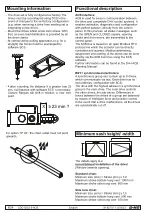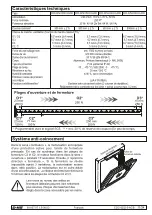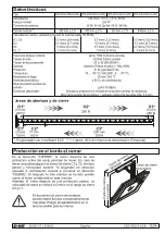
Minimum sash height/ -width
The details apply to a
non-rotational installation of the drive!
(Window inwards opening)
Standard chain:
Minimum size (mm) = Stroke (mm) x 3.9
Maximum stroke bottom-hung vent: 1000 mm
Maximum stroke side-hung vent: 800 mm
Side bow chain:
Minimum size (mm) = Stroke (mm) x 1,6
Maximum stroke bottom-hung vent: 800 mm
Maximum stroke side-hung vent: 350 mm
x
x
99.827.07 1.5/09/23
CDC-0252-5-ACB
CDC-0252-5-ACB
8/24
9/24
99.827.07 1.5/09/23
Troubleshooting
English
English
Maintenance and cleaning
Maintenance work is only allowed when the device is in
a de-energized condition! Inspection and maintenance
has to be carried out according to D+H maintenance
notes. Only original D+H spare parts may be used.
Repair is to be carried out exclusively by D+H.
Wipe away debris or contamination with a dry, soft
cloth.
Do not use cleaning agents or solvents.
- The drive set is fully configured ex factory.The
drives must be reconfigured using SCS in the
event of changes to the ex-factory configuration
(e.g. when removing a drive from existing set or
integrating a new drive).
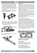
- Mount the drives whilst under zero stress. With
that, an even load distribution is provided by all
the drive chains.
- At vertical active pulling application (e.g. for a
skylight) the forces must be rearranged by
software SCS.
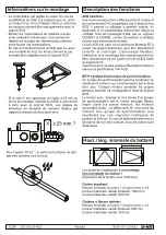
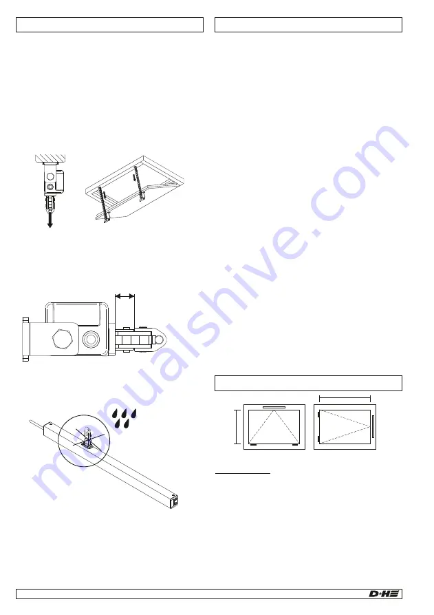
- If after mounting, the distance X is greater than 23
mm, null balance with software SCS is neccesary.
Closure Ranges will shift in relation to new zero
point.
Mounting information
≥ 23 mm ?
X
Functional description
For option “IP 42”: the chain outlet must not point
upwards.
Electrical devices, accessories, batteries and packa-
ging should be sorted for environmental-friendly
recycling. Do not dispose electrical devices and
batteries into household waste!
Only for EC countries:
According the European Guideline 2012/19/EU for
waste electrical and electronic equipment and its
implementation into national right, electrcal devices
that are no longer usable must be collected separa-
tely and disposed of in an environmentally correct
manner.
Disposal
Declaration of Conformity
We declare under our sole responsibility that the
product described under “Technical Data” is in
conformity with the following
:
regulations
2014/30/EU, 2011/65/EU
S.I. 2016/1091, S.I. 2012/3032
Technical file at:
D+H Mechatronic AG, D-22949 Ammersbek
Dirk Dingfelder
Maik Schmees
CEO
CTO
12.09.2023
Visual inspection:
Only one main drive is allowed. The main always
has the highest addressing of all the drives; this
can be found on the type plate of the drive. Subs
are numbered downwards from the main, so that in
a group of two drives, for example, the main is no.
2 (M2) with a sub no. 1 (S1) drive. Please note that
this only applies in the ex-factory configuration. As
soon as the drives are re-addressed with SCS, the
ex-factory addressing no longer applies.
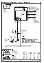
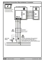
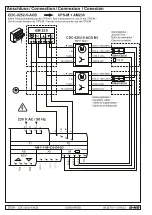
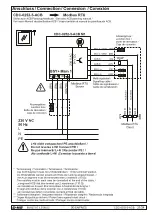
Wiring:
Is the drive or drive group wired properly?
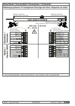
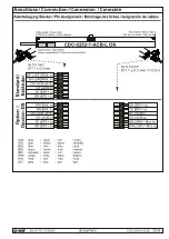
See connection plans.
Diagnostics with SCS software:
The SCS software and a BSY+ interface (BI-BT 2
or BI-USB V3) is required for further
troubleshooting or configuration.
ACB interface:
ACB is used for secure communication between
the drive and compatible D+H control systems. It
enables activation, diagnostics and configuration
with perfect position, directly from the control
panel. In this process, all status messages, such
as the OPEN and CLOSED signals, opening
stroke and drive errors, are transmitted to the
control panel.
The ACB bus is based on an open Modbus RTU
protocol via which the actuator can be directly
controlled and queried. Modbus addressing,
assignment and naming of the drives can be done
directly via the ACB bus lines using the SCS
software.
Further information can be found in the D+H ACB
Planning Manual.
BSY+ synchronised electronics:
A synchronous group can contain up to 8 drives,
which communicate via bus. Each drive has its
own address, configurable with SCS.
The drive with the highest adress in a synchronous
group is the main drive. The main drive controls
the other drives, the sub drives. Differences in
forces between the drives of a group are balanced
by means of intelligent force and position control.
In the event that a drive malfunctions, all the drives
are automatically cut off.


