10
CY3631 WirelessUSB™ Manufacturing Test Kit User Guide, Doc. # 001-66724 Rev. *B
Kit Operation
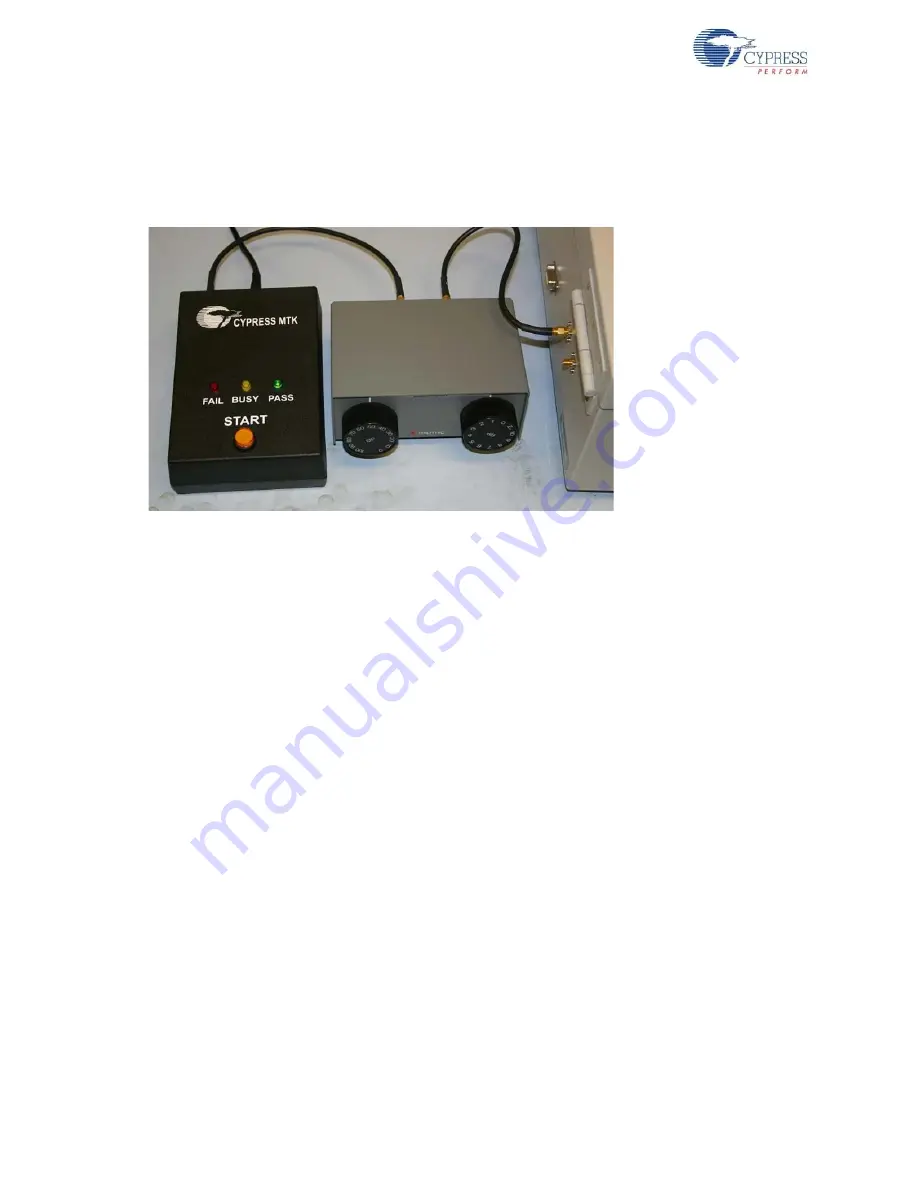
The initial calibration is easily done using a variable attenuator rather than the fixed attenuators
provided in the kit. This is shown in
. If the variable attenuator used does not have
sufficient range, it may be necessary to install both the variable and some fixed attenuation. The
amount of fixed attenuation must be determined by trial and error.
Figure 2-4. Calibration Setup
The calibration begins by testing a known good DUT sample (golden DUT) with a ‘best guess’
attenuation value. Based on our experience, this is typically in the 40 dB range. The test starts, and
should pass at this initial setting. If it does not, the attenuation may need to be reduced by 10 dB. If a
second test with this reduced attenuation still does not pass, check all the connections to be sure
that everything is connected correctly. If this still does not fix the problem, attach the antenna directly
to the SMA on the MTK test fixture and test the golden DUT in free air (no chamber). If this still does
not pass, make sure that the test fixture has power, press the reset button (the self-test should pass
and the green LED remain lit), and make sure that the golden DUT has good batteries installed and
is in MTK test mode.
After a base line is established by passing the test, the attenuation is increased and the test
repeated. Doing this several times, increasing the attenuation each time, eventually reaches the
level where the golden DUT fails the test repeatedly at a given attenuation. There may be an
intermediate attenuation value at which the test passes only sometimes. Use your discretion on how
to determine the limit value. One option is to consider the test passing (for calibration only) if it
passes three or more of five tests. As long as the method used is consistent, the results will be
consistent.
It may be helpful to repeat the test with additional known good units recording the attenuation limit
for each, especially for a new product. Eventually, a “worst of the best” unit can be retained for future
calibration use. This is a unit that, while good and passing all the requirements, exhibits the lowest
attenuation limit ever seen in a good unit.
Now that a limit has been found, the fixed attenuation should be installed in the cable. The total
attenuation should be selected such that it is lower than the limit value found using the golden units
by some guard band (–3 dB, for example.) The type of defect results in far greater than 3 dB of
reduction in either transmit power or receive sensitivity.
Finally, the golden DUT should be tested once more with the fixed attenuation installed to ensure
that the setup is still working. The test should pass repeatedly. If it does not, check the attenuation
value and all connections again.


