


7
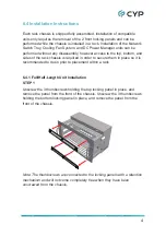
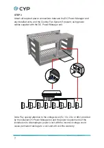
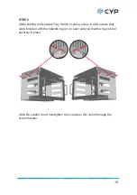
STEP 3
Attach all required power connections between the DC Power Manager and
any installed units, and the Cooling Fan System if present, using power
cables supplied with the DC Power Manager unit.
SERV. CONTROL
1
- +
2
- +
3
- +
4
- +
5
- +
6
- +
7
- +
8
FAN
- +
A B 12V
5V POWER OUT
OFF
ON
-
+
DC 12V
1
2
3
4
5
6
7
8
SER
V. CONTROL
1
- +
2
- +
3
- +
4
- +
5
- +
6
- +
7
- +
8
FAN
- +
A B12V
5V POWER OUT
OFF
ON
-
+
DC 12V
LAN
CAT5e/6/7 OUT
DC 5V
LAN
CAT5e/6/7 OUT
DC 5V
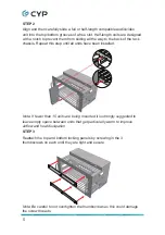
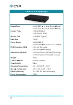
Note: Pay special attention to the voltage level (5v, 12v, 24v, or 48v) provided
by the installed DC Power Manager(s) and the power requirements of the
installed units. Attempting to power a unit with the incorrect voltage could
cause permanent damage to a unit and will void the warranty.
Summary of Contents for CSR-G6400
Page 2: ......
Page 25: ......
Page 26: ......
Page 27: ......
Page 28: ...CYPRESS TECHNOLOGY CO LTD www cypress com tw ...