background image

27

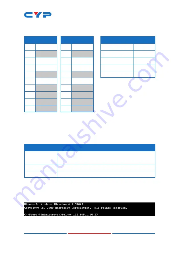
6.7 RS-232 Control

UNIT

TERMINAL

SERIAL PORT SETTINGS

Pin

Pinout

Pin

Pinout

Baud Rate

115200

1

1

Data Bits

8

2

TxD

2

RxD

Parity Bit

None

3

RxD

3

TxD

Stop Bits

1

4

4

Flow Control

None

5

GND

5

GND

6

6

7

7

8

8

9

9

6.8 Telnet Control

Before attempting to use Telnet control, please ensure that both the 

unit and the PC are connected to the same active networks.

To Access the Command Line Interface (CLI)

Windows 7

Click 

Start

, type “cmd” in the search field, and 

press 

Enter

.

Windows XP

Click 

Start

 > 

Run

, type “cmd”, and press 

Enter

.

Mac OS X

Click 

Go

 > 

Application

s > 

Utilities

 > 

Terminal

.

Once in the Command Line Interface (CLI) type “

telnet

” followed by 

the IP address of the unit (and the port number if it is non-standard) 

and then hit “Enter”. This will connect us to the unit we wish to control. 

Type “

help

” to list the available commands. See below for reference.

Note: If the IP address is changed then the IP address required for 

Telnet access will also change accordingly.

Summary of Contents for CSC-5501TX

Page 1: ...CSC 5501TX HDMI DP VGA to HDMI HDBaseT Scaler PSE with Optical Audio Return Operation Manual Operation Manual ...

Page 2: ......

Page 3: ...echnology reserves the right to make improvements to this document and or product at any time and without notice COPYRIGHT NOTICE No part of this document may be reproduced transmitted transcribed stored in a retrieval system or any of its part translated into any language or computer file in any form or by any means electronic mechanical magnetic optical chemical manual or otherwise without expre...

Page 4: ...mpty slots in the unit as you may damage parts inside the unit Do not attach the power supply cabling to building surfaces Use only the supplied power supply unit PSU Do not use the PSU if it is damaged Do not allow anything to rest on the power cabling or allow any weight to be placed upon it or any person walk on it To protect the unit from overheating do not block any vents or openings in the u...

Page 5: ... Rear Panel 4 6 3 Remote Control 6 6 4 IR Cable Pinouts 6 6 5 OSD Menu 7 6 6 WebGUI Control 22 6 6 1 Main Page 0 23 6 6 2 Main Page 1 25 6 7 RS 232 Control 27 6 8 Telnet Control 27 6 9 RS 232 and Telnet Commands 28 7 Connection Diagram 48 8 Specifications 49 8 1 Technical Specifications 49 8 2 Video Specifications 50 8 3 Audio Specifications 52 9 Acronyms 53 ...

Page 6: ...itting optical audio from a compatible HDBaseT Receiver to this unit for local playback An integrated audio DSP with gain control for routing audio and controlling background audio levels adds to the versatility of this product The HDBaseT output can provide 48V PoH to power to compatible HDBaseT Receivers The unit can be controlled via front panel buttons with an On Screen Display OSD WebGUI IR r...

Page 7: ...DMI 2 VGA and 3 stereo audio Mirrored HDMI and HDBaseT outputs Supports input and output resolutions up to 1080p WUXGA RB Analog stereo and digital coaxial breakout audio outputs Supports pass through of LPCM 2 0 audio Supports the Optical Audio Return OAR function to transmit audio from a compatible HDBaseT receiver to this unit Audio DSP with gain control for routing audio and controlling backgr...

Page 8: ...h source is currently selected 4 MENU Button Press to enter the OSD menu or to back out from menu items Note Pressing and holding the MENU button while connecting the power supply will reset all settings to the factory defaults Pressing MENU and together will reset the output resolution to XGA 1024 768 60Hz Pressing Menu and together will reset the output resolution to 720p 60Hz 5 Buttons Press to...

Page 9: ...vices such as CD players or PCs Note In Audio Follows Video mode Audio 1 maps to the digital inputs DisplayPort HDMI 1 HDMI 2 Audio 2 maps to VGA 1 and Audio 3 maps to VGA 2 2 HDMI OUT Connect to HDMI TVs monitors or amplifiers for digital video and audio output AUDIO OUT Connect to powered speakers or an amplifier for stereo analog audio output COAX OUT Connect to powered speakers or an amplifier...

Page 10: ...ct to a compatible HDBaseT Receiver with a single Cat 5e 6 7 cable for transmission of all data signals 8 LAN Connect directly or through a network switch to your PC laptop to control the unit via Telnet WebGUI and to extend the network to both ends of the HDBaseT connection 9 RS 232 Connect directly to a PC laptop or other serial control device to send RS 232 commands to control the unit 10 SERVI...

Page 11: ... 5 OK VOL Press OK to confirm the selection or press the arrow buttons to navigate the OSD menu When the OSD menu is not active use the LEFT RIGHT buttons to control the volume level 6 AUTO ADJUST Press this button to activate the Auto Adjust function for VGA sources 7 RESET Press this button to reset the device back to the default settings 6 4 IR Cable Pinouts 3 1 2 Infrared Power Ground IR Exten...

Page 12: ...e Menu button to back out from any menu item and then press it again to close the menu MAIN MENU Video Picture Audio OSD Ethernet EDID Reset FW Update Information The individual functions of the OSD will be introduced in the following section Items marked in BOLD are the factory default settings VIDEO 2ND LEVEL 3RD LEVEL 4TH LEVEL Video Routing DP HDMI1 HDMI2 VGA1 VGA2 Output Native CAT5e 6 Native...

Page 13: ...0 60 1280 1024 60 1440 900 60 1400 1050 60 1680 1050 60 1600 1200 60 1920 1080 60 1920 1200 60 720 480p 60 1280 720p 60 1920 1080p 60 720 576p 50 1280 720p 50 1920 1080p 50 1920 1080p 24 1920 1080p 25 1920 1080p 30 Aspect Overscan FULL Best Fit Pan Scan Letterbox Under 2 Under 1 Follow In ...

Page 14: ...ER TO DISPLAY HDMI1 HDCP Off Refer To Source REFER TO DISPLAY HDMI2 HDCP Off Refer To Source REFER TO DISPLAY No Signal Color BLACK White Blue Red Green Blank OFF On Freeze OFF On Auto Setup Auto Sync Off OFF 30s 60s 3 Min 5 Min 10 Min Auto Scan OFF On From DP From HDMI1 ...

Page 15: ...ing the source Full stretches the source to fill the output resolution regardless of the original aspect ratio while Best Fit will always attempt to retain the original source s correct aspect ratio by adding black bars if necessary Follow In centers the source on the screen without any scaling 1 1 pixel reproduction 4 DP HDCP Selects the HDCP logic to use with the DisplayPort input Setting this t...

Page 16: ...urce loss feature Selecting a specific input will force the search to begin with that input Auto Switch Enable or disable automatically switching to any newly detected source 11 VGA Setup These settings control the input specifications to use with the VGA inputs Activating the Auto Setup function forces the unit to attempt to detect the correct values Selecting reset will reset all VGA input setti...

Page 17: ...image 4 Contrast Provides control over the overall contrast of the scaled output image 5 Hue Provides control over the hue shift of the scaled output image 6 Saturation Provides control over the color saturation level of the scaled output image 7 Sharpness Provides control over the amount of sharpness processing to apply to the scaled output image 8 NR Provides control over the aggressiveness of t...

Page 18: ...OLLOW VIDEO Audio 1 Audio 2 Audio 3 HDMI Volume 0 100 80 Coax Volume 0 100 80 Analog Volume 0 100 80 HDMI Mute OFF On Coax Mute OFF On Analog Mute OFF On Audio Delay OFF 30ms 40ms 50ms 60ms 70ms 80ms 90ms 100ms 110ms 120ms 130ms 140ms 150ms 160ms ...

Page 19: ...the selected video source Note In Follow Video mode digital inputs will only use the analog audio if no digital audio is detected from the selected source 2 HDMI Volume Provides control over the HDMI HDBaseT output s volume level 3 Coax Volume Provides control over the coaxial audio output s volume level 4 Analog Volume Provides control over the analog audio output s volume level 5 HDMI Mute Mutes...

Page 20: ...ble audio delay for the coaxial audio output 11 Analog Audio Delay Enable or disable audio delay for the analog audio output 12 Reset Audio Selecting this will reset all audio settings back to their factory defaults OSD 2ND LEVEL 3RD LEVEL H Position 0 60 30 V Position 0 60 30 Timer OFF 5s 10s 15s 20s 25s 30s 35s 40s 45s 50s 55s 60s Transparent 0 50 50 Display Off On 5S 10s ...

Page 21: ...th of time for the information display to be visible after a source or resolution change 6 Reset OSD Selecting this will reset all OSD settings back to their factory defaults ETHERNET 2ND LEVEL 3RD LEVEL IP Mode STATIC DHCP Telnet Login OFF On Setup Static IP Static IP 192 168 1 50 Mask 255 255 255 0 Gate 192 168 1 254 IP Current Status MAC 1 IP Mode Select the IP address acquisition mode When the...

Page 22: ...dress 5 MAC Displays the unit s MAC address EDID 2ND LEVEL 3RD LEVEL DP EDID 1024 768 60 1280 800 60 1280 1024 60 1366 768 60 1440 900 60 1400 1050 60 1600 900 60 1600 1200 60 1680 1050 60 1920 1200 60 1280 720p 50 1280 720p 60 1920 1080p 50 1920 1080p 60 INT1 User1 User2 User3 Out HDMI Out CAT5e 6 HDMI1 EDID 1024 768 60 1280 800 60 1280 1024 60 1366 768 60 ...

Page 23: ...60 1680 1050 60 1920 1200 60 1280 720p 50 1280 720p 60 1920 1080p 50 1920 1080p 60 INT1 User1 User2 User3 Out HDMI Out CAT5e 6 HDMI2 EDID 1024 768 60 1280 800 60 1280 1024 60 1366 768 60 1440 900 60 1400 1050 60 1600 900 60 1600 1200 60 1680 1050 60 1920 1200 60 1280 720p 50 1280 720p 60 ...

Page 24: ...r2 User3 Out HDMI Out CAT5e 6 VGA1 EDID 1024 768 60 1280 800 60 1280 1024 60 1366 768 60 1440 900 60 1400 1050 60 1600 900 60 1600 1200 60 1680 1050 60 1920 1200 60 1280 720p 50 1280 720p 60 1920 1080p 50 1920 1080p 60 INT2 User4 User5 VGA2 EDID 1024 768 60 1280 800 60 1280 1024 60 ...

Page 25: ...ion HDMI1 EDID Status HDMI2 EDID Status VGA1 EDID Status VGA2 EDID Status 1 DP EDID Select the EDID to use with the DisplayPort input 2 HDMI1 EDID Select the EDID to use with the HDMI 1 input 3 HDMI2 EDID Select the EDID to use with the HDMI 2 input 4 VGA1 EDID Select the EDID to use with the VGA 1 input 5 VGA2 EDID Select the EDID to use with the VGA 2 input 6 DP HDMI VGA EDID Status Displays the...

Page 26: ... a way to update the unit s firmware Insert a USB thumb drive with a valid firmware file bin format in the root directory into the unit s USB service port then select this option After the update is complete the unit will automatically reboot INFORMATION 2ND LEVEL 3RD LEVEL Video Current Status Details Input Out HDMI Out CAT5e 6 Source HDCP Sink HDMI HDCP Sink CAT5e 6 HDCP Version 1 Information Th...

Page 27: ...e listed devices you will be presented with the network details of that particular device 1 IP Mode If you choose you can alter the static IP network settings for the device or switch the unit into DHCP mode to automatically obtain proper network settings from a local DHCP server To switch to DHCP mode please select DHCP from the IP mode drop down then click Save followed by Reboot 2 WebGUI Hotkey...

Page 28: ...n Page 0 All primary functions of this unit are controllable via the built in WebGUI This control is presented across 2 separate tabs MainPage0 and MainPage1 After logging in the browser will display the unit s primary control tab MainPage0 to allow direct control of the unit If desired the numerical value for many of the items can be entered directly by typing it in the box above the slider bar P...

Page 29: ...oise reduction To return these settings to their defaults click on the Reset Picture EXE button VGA This section allows for direct control of the H position V position phase and clock used by the current VGA input These settings can be automatically configured by clicking on the Auto Setup EXE button To return these settings to their defaults click on the Reset EXE button Note The VGA section is o...

Page 30: ...independently When the Audio Source is set to Follow Video the analog audio inputs are mapped as follows Audio 1 Digital video DisplayPort HDMI 1 and HDMI 2 Audio 2 VGA 1 Audio 3 VGA 2 Note All audio output types share the same unified delay value when audio delay is enabled OSD This section lets the user change the H V positioning of the OSD the display timeout timer and OSD window transparency T...

Page 31: ...also change accordingly Consult the OSD to view the current IP settings if necessary FWUPDATE This section allows for new firmware to be uploaded into the unit To update the unit s firmware click the Choose File button to open the file selection window and then select an appropriate firmware update file bin format located on your local PC After selecting the file click the Upload button to begin t...

Page 32: ... Command Line Interface CLI Windows 7 Click Start type cmd in the search field and press Enter Windows XP Click Start Run type cmd and press Enter Mac OS X Click Go Applications Utilities Terminal Once in the Command Line Interface CLI type telnet followed by the IP address of the unit and the port number if it is non standard and then hit Enter This will connect us to the unit we wish to control ...

Page 33: ...DEFAULT Reset all configurations to the factory defaults GET MODEL NAME Show the unit s model name GET FW VERSION Show the unit s current firmware version GET INPUT PORT NUMBER Report the number of inputs supported by the unit GET OUTPUT PORT NUMBER Report the number of outputs supported by the unit SET POWER N1 Turn the unit on or off stand by mode Available values for N1 0 Off Stand by mode 1 On...

Page 34: ...DR N1 Set the static IP address N1 X X X X X 0 255 GET IP ADDR Show the current IP address GET STATIC IP ADDRESS Show the current static IP address SET NETMASK N1 Set the static netmask address N1 X X X X X 0 255 GET NETMASK Show the current netmask SET GATEWAY N1 Set the static gateway address N1 X X X X X 0 255 GET GATEWAY Show the current gateway GET MAC ADDR Show the MAC address ...

Page 35: ...vailable values for N1 4 VGA 1 5 VGA 2 ALL All 2 analog inputs GET INT EDID N1 DATA List Internal EDID N1 s EDID data in ASCII HEX N1 1 2 Internal EDID number SET NATIVE EDID N1 TO INPUT N2 Assign Native EDID N1 to input N2 Available values for N1 0 1024 768 60 EDID 1 1280 800 60 EDID 2 1280 1024 60 EDID 3 1366 768 60 EDID 4 1440 900 60 EDID 5 1400 1050 60 EDID 6 1600 900 60 EDID 7 1600 1200 60 ED...

Page 36: ...1 5 VGA 2 ALL All inputs SET USER EDID N1 TO INPUT N2 Assign User EDID N1 to input N2 Available values for N1 1 User EDID 1 2 User EDID 2 3 User EDID 3 4 User EDID 4 5 User EDID 5 Available values for N2 1 DisplayPort 2 HDMI 1 3 HDMI 2 4 VGA 1 5 VGA 2 ALL All valid inputs Note User EDIDs 1 3 can only be assigned to digital inputs User EDIDs 4 5 can only be assigned to analog inputs ...

Page 37: ...Available values for N1 A HDMI output B HDBaseT output Available values for N2 1 DisplayPort 2 HDMI 1 3 HDMI 2 ALL All digital inputs GET SINK EDID N1 DATA List output N1 s EDID data in ASCII HEX Available values for N1 A HDMI output B HDBaseT output GET INPUT EDID N1 DATA List input N1 s assigned EDID data in ASCII HEX Available values for N1 1 DisplayPort 2 HDMI 1 3 HDMI 2 4 VGA 1 5 VGA 2 ...

Page 38: ...es for N2 0 Off 1 Refer to source 2 Refer to display GET INPUT N1 HDCP MODE Show the HDCP handling method currently used by input N1 Available values for N1 1 DisplayPort 2 HDMI 1 3 HDMI 2 SET AUDIO ROUTE N1 Set the audio routing method Available values for N1 0 Follow video 1 Analog audio 1 2 Analog audio 2 3 Analog audio 3 GET AUDIO ROUTE Show the current audio routing setting ...

Page 39: ... Off 1 On GET AUDIO N1 MUTE Show the current audio mute setting for output type N1 Available values for N1 A HDMI B Coaxial C Analog audio SET AUDIO ALL MUTE N1 Enable or disable audio muting for all output types Available values for N1 0 Off 1 On SET AUDIO N1 VOLUME N2 Set the audio volume for output type N1 Available values for N1 A HDMI B Coaxial C Analog audio N2 0 100 Volume level ...

Page 40: ... N1 VOLUME DOWN Decrease the volume of audio type N1 by 1 unit Available values for N1 A HDMI B Coaxial C Analog audio GET AUDIO N1 VOLUME Show the current volume setting for output type N1 Available values for N1 A HDMI B Coaxial C Analog audio SET AUDIO DELAY N1 Set the global audio delay setting Available values for N1 0 Off 1 30ms 2 40ms 3 50ms 4 60ms 5 70ms 6 80ms ...

Page 41: ...AY Show the current global audio delay setting SET AUDIO N1 DELAY ENABLE N2 Enable or disable audio delay on output type N1 Available values for N1 A HDMI B Coaxial C Analog audio Available values for N2 0 Off 1 On GET AUDIO N1 DELAY ENABLE Show the current audio delay setting for output type N1 Available values for N1 A HDMI B Coaxial C Analog audio ...

Page 42: ...Show the current input source GET SCALER A INPUT TIMING Show the video timing of the current input source SET SCALER A OUTPUT TIMING N1 Set the scaled output resolution Available values for N1 0 Native Cat 5e 6 1 Native HDMI 2 640 480 60Hz 3 800 600 60Hz 4 1024 768 60Hz 5 1280 768 60Hz 6 1360 768 60Hz 7 1280 720 60Hz 8 1280 800 60Hz 9 1280 1024 60Hz 10 1440 900 60Hz 11 1400 1050 60Hz ...

Page 43: ...p 50Hz 21 1920 1080p 50Hz 22 1920 1080p 24Hz 23 1920 1080p 25Hz 24 1920 1080p 30Hz GET SCALER A OUTPUT TIMING Show the current scaled output resolution SET SCALER A ASPECT RATIO N1 Set the output aspect ratio Available values for N1 0 Overscan 1 Full 2 Best fit 3 Pan scan 4 Letterbox 5 Underscan 2 6 Underscan 1 7 Follow input GET SCALER A ASPECT RATIO Show the current output aspect ratio ...

Page 44: ...ALER A AUTO SYNC OFF Show the current auto sync off function s setting SET SCALER A NO SIGNAL COLOR N1 Set the free run color to use when there is no live source Available values for N1 0 Black 1 White 2 Blue 3 Red 4 Green GET SCALER A NO SIGNAL COLOR Show the currently selected free run color SET SCALER A BLANK N1 Enable or disable blanking the video audio output Available values for N1 0 Off 1 O...

Page 45: ...SCALER A FREEZE Show the current video freeze function s state SET INPUT AUTO SCAN N1 Enable or disable the auto scan on signal loss function Selecting a specific input will force the scan to begin with that input Available values for N1 0 Off 1 On 2 DisplayPort 3 HDMI 1 4 HDMI 2 5 VGA 1 6 VGA 2 GET INPUT AUTO SCAN Show the current auto scan setting SET INPUT AUTO SWITCH N1 Enable or disable the a...

Page 46: ...dge to edge image to accurately judge the dimensions of the signal GET INPUT N1 VGA AUTO Show the current status of the VGA auto setup function on input N1 Available values for N1 4 VGA 1 5 VGA 2 SET INPUT N1 VGA H POSITION N2 Set the horizontal position for input N1 VGA inputs only Available values for N1 4 VGA 1 5 VGA 2 N2 0 250 Horizontal position GET INPUT N1 VGA H POSITION Show the current ho...

Page 47: ... current vertical position of input N1 Available values for N1 4 VGA 1 5 VGA 2 SET INPUT N1 VGA PHASE N2 Set the phase for input N1 VGA inputs only Available values for N1 4 VGA 1 5 VGA 2 N2 0 250 Phase GET INPUT N1 VGA PHASE Show the current phase of input N1 Available values for N1 4 VGA 1 5 VGA 2 SET INPUT N1 VGA CLOCK N1 Set the clock for input N1 VGA inputs only Available values for N1 4 VGA ...

Page 48: ...N1 Set the horizontal position of the OSD N1 0 60 Horizontal position GET SCALER A OSD H POSITION Show the current horizontal position of the OSD SET SCALER A OSD V POSITION N1 Set the vertical position of the OSD N1 0 60 Vertical position GET SCALER A OSD V POSITION Show the current vertical position of the OSD SET SCALER A OSD TIMEOUT N1 Set the OSD menu timeout length or disable the timeout Ava...

Page 49: ...e OSD menu N1 0 50 Transparency GET SCALER A OSD TRANSPARENCY Show the current OSD menu transparency level SET SCALER A OSD INFO DISPLAY N1 Enable disable or set a timeout for the OSD information display Available values for N1 0 Off 1 On 2 5 seconds 3 10 seconds GET SCALER A OSD INFO DISPLAY Show the current OSD information display setting SET SCALER A R GAIN N1 Set the output s red gain level N1...

Page 50: ...w the current blue gain output level SET SCALER A R OFFSET N1 Set the output s red offset level N1 0 1023 Red offset GET SCALER A R OFFSET Show the current red offset output level SET SCALER A G OFFSET N1 Set the output s green offset level N1 0 1023 Green offset GET SCALER A G OFFSET Show the current green offset output level SET SCALER A B OFFSET N1 Set the output s blue offset level N1 0 1023 B...

Page 51: ...CALER A CONTRAST Show the output s current contrast level SET SCALER A HUE N1 Set the output s hue setting N1 0 60 Hue GET SCALER A HUE Show the output s current hue setting SET SCALER A SATURATION N1 Set the output s saturation level N1 0 60 Saturation GET SCALER A SATURATION Show the output s current saturation level SET SCALER A SHARPNESS N1 Set the output s sharpness level N1 0 63 Sharpness GE...

Page 52: ...e 3 High 4 Auto GET SCALER A NR Show the current noise reduction setting Note 1 Commands will not be executed unless followed by a carriage return Commands are not case sensitive Spaces between command segments are not required Note 2 Certain commands include the characters These characters must be included where indicated for the command to be accepted ...

Page 53: ... OUT CAT5e 6 7 IN POWER OPT IN IR IN 1 IR OUT 2 RS 232 TX RX UPDATE 1 5m 60 7m 3m 3m 60 IR In IR Out RS 232 Controlled Device Remote Zone HDMI Output HDBaseT Output HDMI Inputs DP Analog Audio Inputs Digital Analog Audio Outputs VGA Analog Audio Inputs Network Switch RS 232 Control System LAN RS 232 RS 232 PC Laptop Media Player AV Receiver Power Supply HDTV Smart TV Media Player PC Laptop PC Lapt...

Page 54: ... S PDIF RCA 1 Stereo 3 5mm Pass through Ports 1 IR Extender 3 5mm 1 IR Blaster 3 5mm 1 RS 232 Terminal Block Pass through Control Port 1 LAN RJ 45 Control Port 1 RS 232 9 pin D sub IR Frequency 30 50kHz 30 60kHz under ideal conditions Baud Rate Up to 115200bps Cat 5e 6 7 Cable Distance 100m 1080p 8 bit Power Supply 24V 2 7A DC US EU standards CE FCC UL certified ESD Protection Human Body Model 8kV...

Page 55: ... C 60 C 4 F 140 F Relative Humidity 20 90 RH Non condensing Power Consumption 18W 8 2 Video Specifications Resolution Timing Hz Support Input Output 640 480 60 72 75 85 60Hz 720 400 85 800 600 56 60 72 75 85 60Hz 1024 768 60 70 75 85 60Hz 1152 864 75 1280 720 60 1280 768 60 75 85 60Hz 1280 800 60 60 RB 60Hz 1280 960 60 1280 1024 60 1280 720p 50 59 94 60 50 60Hz 1280 768 60 75 85 60Hz 1280 800 60 6...

Page 56: ... 60 1400 1050 60 60 RB 60Hz 1440 900 60 60 RB 60Hz 1600 900 60 1600 1200 60 1680 1050 60 60 RB 60Hz 1920 1080 60 60 RB 60Hz 1920 1200 60 RB 720 1440 576i 50 720 1440 480i 59 94 60 720 480p 59 94 60 60Hz 720 576p 50 1920 1080i 50 59 94 60 1920 1080p 23 97 29 97 59 94 1920 1080p 24 25 30 50 60 ...

Page 57: ...ications Analog Inputs Max Audio Level 2Vrms Input Impedance 10kΩ Analog Outputs Max Audio Level 2Vrms THD N 80 1K 0dBFS SNR 70dB 1K 0dBFS Frequency Response 3dB 20Hz 20KHz Crosstalk 60dB 20hz 20Khz Output Impedance 470Ω ...

Page 58: ...Definition HDCP High bandwidth Digital Content Protection HDMI High Definition Multimedia Interface HDTV High Definition Television IP Internet Protocol IR Infrared LAN Local Area Network LPCM Linear Pulse Code Modulation OAR Optical Audio Return OSD On Screen Display PC Personal Computer PD Powered Device PoH Power over HDBaseT PSE Power Sourcing Equipment S PDIF Sony Philips Digital Interface Fo...

Page 59: ...54 ACRONYM COMPLETE TERM VGA Video Graphics Array WUXGA RB Widescreen Ultra Extended Graphics Array Reduced Blanking ...

Page 60: ...CYPRESS TECHNOLOGY CO LTD www cypress com tw ...

Reviews: