background image

4

7

1

2

4

5

6

INPUT

OUTPUT

S-VIDEO

VIDEO

Y

Pb/Cb

Pr/Cr

PC IN

RGB/YPbPr

DC 12V

RS-232

3

       7. Power and LED button: 

Press once to power on the unit, press again to turn it off.


Note:

           * Under picture adjust mode, press 

 and 

simutaneously will revert the selected 

              parameter back to factory preset value. Press both buttons for over 5 seconds. 

              will revert all picture parameters back to their factory preset values.              

           * You can use RS-232 to lockout the front panel controls. To lift this lockout 

              and revert all parameters back to factory preset value, please press "mode" 

              and "picture" buttons simultaneously for over 10 seconds.

       8. IR Sensor: 

Infrared remote control sensor.

       9

Front Panel Lockout:

 Under certain circumstances it may be desirable to disable 

                                                the front panel controls. For example, to prevent

                                                unauthorized or accidental changes to the setting while the

                                                unit is in use. 

                                                To disable the front panel controls use RS-232 to set the 

                                                front panel lockout to ON position.

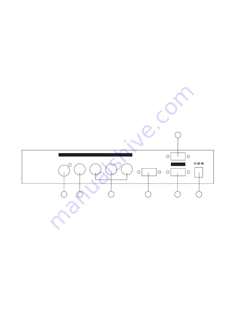
(5). Connecting the Video inputs

       The video scaler can accept a composite video, an S-Video or a YCbCr/YPbPr or PC

       input signal for scaling.

Rear Panel

    1 . 

S-Video:

 Use an S-Video cable to connect the S-Video output of the source video 

                         equipment to the connector labled " S-Video" on the back of the Video

                         Scaler.

                         S-Video provides improved performance over Composite Video and is 

                         recommended over composite.

    2 . 

Composite Video: 

Use a Composite video cable to connect the composite video

                                          output of the source equipment to the connector labeled "Video"

                                          on the back of the Video Scaler.

    3 . 

YCbCr/YPbPr input: 

Use the component cable to connect the component output of

                                            the source video equipment to the connectors labeled

                                            YCbCr/YPbPr on the back of the video scaler.

    4 . 

PC input: 

Connect the source computer's VGA output signal to the HD 15 connector

                          labeled "PC IN" on the back of the Video Scaler.    


Summary of Contents for CSC-220

Page 1: ......

Page 2: ...s below PC output 640x 480 800x 600 SVGA 1024 x768 XGA 1280 x 1024 SXGA HDTV output 480p 576p 720p 1080i 2 Automatically accommodates input video systems of NTSC 3 58 PAL and SECAM 3 High performance...

Page 3: ...ired input source from Video S Video Component or PC inputs Resolution mode If output is selected as RGB press or button to choose from 640 x 480 VGA 800 x 600 SVGA 1024 x 768 XGA or 1280 x 1024 SXGA...

Page 4: ...Pr source and the built in yellow led will illuminate when it s selected PC Press this button to select the PC source and the built in yellow led will illuminate when it s selected 5 Output Resolution...

Page 5: ...es to the setting while the unit is in use To disable the front panel controls use RS 232 to set the front panel lockout to ON position 5 Connecting the Video inputs The video scaler can accept a comp...

Page 6: ...r output 480p 576p 720p 1080i is selected use the HD 15 to YPbPr 3 x RCA cable to connect the output to the YPbPr input of your HDTV display Note Use of wrong cable for your selected output will resul...

Page 7: ...as output resolution 12 576p Press the button to select 852 x 576p as output resolution 13 720p Press the button to select 1280 x 720p as output resolution 14 1080i Press the button to select 1920 x 1...

Page 8: ...ontact Cypress Technology Support A disk is provided with the CSC 220 containing a sample Windows Control Panel that permits remote control of the unit from a PC via RS 232 Note The connection between...

Page 9: ...D1 OSD1 OSD on DISPLAY0 DISPLAY0 Display off DISPLAY1 DISPLAY1 Display on IR0 IR0 IR sensor off IR1 IR1 IR sensor on PANEL0 PANEL0 Fromt panel lockout on PANEL1 PANEL1 Fromt panel lockout off COMB0 CO...

Page 10: ...site video on BNC S Video on 4 pin Mini DIN Component on BNC Pixels Format Scan VGA 640 x 480 SVGA 800 x 600 XGA 1024 x 768 SXGA 1280 x 1024 16 9 1280 x 720p 720p 16 9 1920 x 1080i 1080i 852 x 480p 48...

Reviews: