background image

- 16 -

8.2. Check the correct assignment of the cooking zone

Check the correct assignment of the cooking zone to control panel 

touch sensor and temperature sensor of induction coils. 
Set the maximum power (P-booster) of the front left (FL) induction 

cooking zone and then place a pot of water on it. Check whether the 

pot was detected and the water begins to heat up. Wait for the water to 

boil. Turn off the cooking zone, the "H" or "h” symbol should be dis

-

played. If the symbol does not appear, place the pot with water on the 

cooking zone and activate it again.
Repeat the procedure for each cooking zone individually. Pay particular 

attention if the "H" or "h" symbol comes on for the cooking zone where 

water was boiled. The symbol displayed for the wrong cooking zone 

indicates incorrect connection of the sensor, which may leading to unit 

damage.

11

4

3

2

5

8

7

6

9

1 — FL cooking zone selection sensor

2 — lower setting sensor

3 — higher setting sensor

4 — FR cooking zone selection sensor

5 — Child lock sensor

6 — RL cooking zone selection sensor

7 — Timer sensor

8 — RR cooking zone selection sensor

9 — ON/OFF sensor

Summary of Contents for 4VI515 Series

Page 1: ...SERVICE MANUAL INDUCTION HOB THIS SERVICE MANUAL IS INTENDED FOR SERVICE TECHNICIANS IS EN 0097 6 10 2018 4VI515 4VI517 set 10132 3 set 10142 3 ...

Page 2: ...7 TEST THE INSULATED GATE BIPOLAR TRANSISTOR IGBT 14 8 CHECK THE CORRECT OPERATION OF THE HOB 15 8 1 CHECK THE CORRECT OPERATION OF THE CONTROL PANEL 15 8 2 CHECK THE CORRECT ASSIGNMENT OF THE COOKING ZONE 16 9 CONNECTION FILTER PCB WITH THE MODULE 17 9 1 CHECK IF NEUTRAL CONDUCTOR FOR L2 PHASE IS CONNECTED CORRECTLY 17 9 2 CHECK IF NEUTRAL CONDUCTOR FOR L1 PHASE IS CONNECTED CORRECTLY 18 9 3 CHEC...

Page 3: ... 3 1 HOB FEATURES AND COMPONENTS ...

Page 4: ...s 1 9 Fan 1 10 FL front left cooking zone coil 1 11 FL cooking zone temperature sensor 1 12 RL rear left cooking zone coil 1 13 RL cooking zone temperature sensor 1 14 RR rear right cooking zone coil 1 15 RR cooking zone temperature sensor 1 16 FR front right cooking zone coil 1 17 FR cooking zone temperature sensor 1 18 Control Panel 2 CHARACTERISTICS OF HOB induction hob with GECO module two hea...

Page 5: ...rs are operational Point 10 6 Are IGBTs operational Replace the induction module while paying special attention to the correct connection of induction coils and temperature sensors Check the connection between filter PCB and induction module PCB Point 10 1 Swap the induction coils Point 12 Check if the E7 error is indicated Check if the E7 error is indicated Point 5 2 Check the correct operation o...

Page 6: ...cial attention to the correct connection of induction coils and temperature sensors Inform the client of an incorrect cooking zone connection or overvoltage note the recommendations according to the service procedure Is the connection correct Check the connection between filter PCB and induction module PCB Point 10 Is the connection correct Check if the correct type induction coils are used Point ...

Page 7: ...ectly End of repair Check the correct operation of the hob Point 9 2 Check the correct operation of the hob Point 9 2 Does the hob operate correctly Does the hob operate correctly End of repair Replace the induction module while paying special attention to the correct connection of induction coils and temperature sensors End of repair Technician should note all defects found in the following list ...

Page 8: ...eck the correct operation of the hob Point 9 2 Replace the induction module while paying special attention to the correct connection of induction coils and temperature sensors Check the connection of cooking zone induction coils and temperature sensors Point 10 7 Is the connection correct Replace the temperature sensor for the cooking zone which indicates E symbol End of repair Before the repair m...

Page 9: ...ify cooking zones temperature sensors con nections as shown in diagram if it s done correctly replace the sensor of cooking zone where error displayed 3 6 Error E5 1 Communication error between control panel and hab module HG361 01 8065761 Solution Check the connection If errror still exist replace the hab module 8065761 3 7 Damaged fan Symptoms Auto switching off the hob after few seconds of work...

Page 10: ...rrent regulations the supply voltagemust be in the specified range depending on the country Country Tolerance Minimum voltage V Maximum voltage V PL 230V 15 10 195 253 DE CS SK ES LT RO BG MD UA RU 230V 10 10 207 253 RU 230V 10 10 220V 10 10 207 198 253 242 UK IE 230V 6 10 216 2 253 DK NO FI SE 230V 10 10V 220 240 AM 220V 10 10V 210 230 KK GE 230V 10 10V 210 230 AZ 220V 10 10 198 242 According to ...

Page 11: ...the measurement using a multimeter by applying multimeter probes to terminals L2 and N 5 CHECK FOR WHICH COOKING ZONES THE E7 MESSAGE IS SHOWN 5 1 Procedure Turn on the hob with the ON OFF sensor Turn off the hob with the ON OFF sensor Wait at least 60 seconds Turn on the hob with the ON OFF sensor Put a pan of water on the left front FL cooking zone Set FL cooking zone heat setting to 9 Wait 20 s...

Page 12: ...FR front right 160mm 6 CHECK THE COIL TYPE 210 mm induction coils large cooking zones with a suitable number of turns are used in the P 4VI515FTB4P3 induction hob Adjacent coils with a differing number of turns are used in induction hobs of different specification If you install a coil with the wrong number of turns in the hob this will lead to malfunction or damage to the induction module Inducti...

Page 13: ... 13 2 single coils 6 dual coils 5 single coils ...

Page 14: ...circuit continuity func tion a beep is heard when the circuit is continuous and then check whether there is an electrical connection between the IGBT terminals Repeat the same procedure for all four IGBTs If there is an electrical connection the meter beeps between any IGBT terminals the IGBT is faulty ...

Page 15: ...he heat setting RL cooking zone selection sensor selects the RL cooking zones to allow setting the heat setting RR cooking zone selection sensor selects the RR cooking zones to allow setting the heat setting FR cooking zone selection sensor selects the FR cooking zones to allow setting the heat setting Higher setting sensor allows you to increase the power and timer settings Lower setting sensor a...

Page 16: ... played If the symbol does not appear place the pot with water on the cooking zone and activate it again Repeat the procedure for each cooking zone individually Pay particular attention if the H or h symbol comes on for the cooking zone where water was boiled The symbol displayed for the wrong cooking zone indicates incorrect connection of the sensor which may leading to unit damage 1 1 4 3 2 5 8 ...

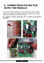
Page 17: ...he multimeter to circuit continu ity function a beep is heard when the circuit is continuous and then check whether there is an electrical connection between the individual terminals of filter PCB and induction module 9 1 Check if neutral conductor for L2 phase is connected correctly ...

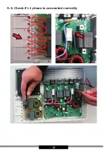
Page 18: ... 18 9 2 Check if neutral conductor for L1 phase is connected correctly ...

Page 19: ... 19 9 3 Check if L1 phase is connected correctly ...

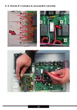
Page 20: ... 20 9 4 Check if L2 phase is connected correctly ...

Page 21: ... 21 9 5 Check if coils are connected correctly ...

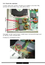
Page 22: ...he varistors Varistors are located on the filter PCB and can be of any colour e g red yellow blue Damaged varistor usually shows visible traces of physical damage such as tearing cracks delamination Example of a damaged varistor Varistor Varistor ...

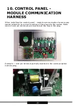
Page 23: ... the control panel module communication harness pay special attention to correct insertion of the plug into the socket Make sure all wire pin terminals are inserted all the way in the plug Example wire pin terminal partially inserted in the communication harness plug ...

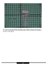
Page 24: ... 24 For correct communication between the module and the control pan el with no disruptions the communication harness must be routed as shown in the photo ...

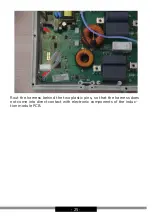
Page 25: ... 25 Rout the harness behind the two plastic pins so that the harness does not come into direct contact with electronic components of the induc tion module PCB ...

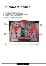
Page 26: ...screw the induction coil wires Disconnect the NTC temperature sensors Swap the large induction coils Swap the small induction coils Connect the temperature sensors as shown in diagram DOK 3 7 Tighten the induction coil wires as shown in diagram DOK 3 7 ...

Page 27: ... 27 12 POTS The surface coming into contact with ceramic glass should be uniform without any indentation or spot application of ferromagnetic material POTS DETECTED POTS UNDETECTED ...

Page 28: ...serwis dokumentacja amica com pl ...

Reviews: