- 10 -
4. CHECK THE CONNECTION
4.1. Connect the power supply
1N
2N
4.2. Measure the L1 phase supply voltage
Perform the measurement using a multimeter, applying multimeter
probes to terminals L1 and N.
In accordance with the current regulations the supply voltagemust be
in the specified range, depending on the country:
Country
Tolerance
Minimum voltage [V]
Maximum voltage [V]
PL
230V (-15/+10%)
195
253
DE / CS / SK / ES /
LT / RO / BG / MD /
UA / RU
230V (-10/+10%)
207
253
RU
230V (-10/+10%)*
220V (-10/+10%)*
207
198
253
242
UK / IE
230V (-6/+10%)
216,2
253
DK / NO / FI / SE
230V (-10/+10V)
220
240
AM
220V (-10/+10V)
210
230
KK / GE /
230V (-10 /+10V)
210
230
AZ
220V (-10/+10%)
198
242
*According to the region
Jumper bar
Summary of Contents for 4VI515 Series
Page 3: ... 3 1 HOB FEATURES AND COMPONENTS ...
Page 13: ... 13 2 single coils 6 dual coils 5 single coils ...
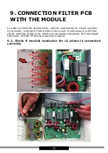
Page 18: ... 18 9 2 Check if neutral conductor for L1 phase is connected correctly ...
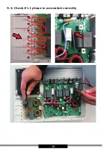
Page 19: ... 19 9 3 Check if L1 phase is connected correctly ...
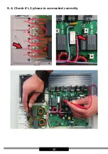
Page 20: ... 20 9 4 Check if L2 phase is connected correctly ...
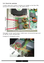
Page 21: ... 21 9 5 Check if coils are connected correctly ...


