background image

System parameter setting


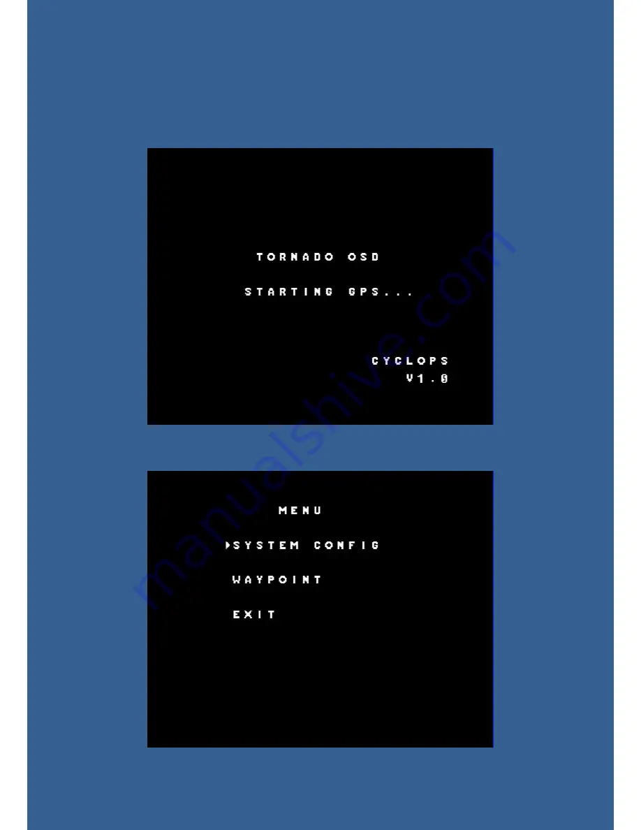
Connect the GPS module and OSD correctly according to the above instructions, 
switch on the power, the red light on the OSD main board flashes, then it will enter 
the following boot interface: 


Press the “UP” and “DOWN” buttons on the switchboard at the same time to enter 
the main menu settings. Press the "UP" or "DOWN" can move the cursor, "OK" button 
used to confirm the options. 


Summary of Contents for tornado osd series

Page 1: ...for using power batteries which must be 12V or 3S LIPO batteries remove the jumper cap and connect 2 and 3 to power up OSD and wireless video equipment separately with additional 12V power supply When...

Page 2: ...Current sensor wiring Diagrams with a T plug GPS Module Installation...

Page 3: ...ctions switch on the power the red light on the OSD main board flashes then it will enter the following boot interface Press the UP and DOWN buttons on the switchboard at the same time to enter the ma...

Page 4: ...SYSTEM CONFIG setup instructions...

Page 5: ......

Page 6: ...nsmitter TRIM Fine adjustment of main board installation levelness Put the model aircraft with TORNADO OSD flat and power it on observe posture angle parameters at the surface If due to the installati...

Page 7: ...disable it LOW POWER RTH Low voltage protection automatically return to home In PA or AUTOPILOT when power voltage lower setting value automatically RTH until user switch back to manual flight mode PA...

Page 8: ...WAYPOINT setup instructions...

Page 9: ...th the due north setting range 0 359 ALT Altitude of waypoint Setting range 0 800 meters ON OFF Whether to use the waypoint PAGE 4 RAD Hovering flight radius The hovering radius with the certain waypo...

Page 10: ...planes the nose cone often provides a perfect mounting location as shown in Figure 1 1 4 As GPS beginning to search satellites the satellite number is indicated by the GPS strength icon on the upper...

Page 11: ...ngle of the plane The location of plane is based on the take off as the base point and rotates from due north from 0 to 360 degree For example if the plane is at the southeast direction it will displa...

Page 12: ...consequent damage due to this operation 13 Screen Display Control Surface DIS port can be connected to any switch on the remote control unit to switch between fighter and concise surfaces In concise s...

Page 13: ......

Page 14: ......

Page 15: ...he elevator or aileron joystick the lock symbol disappears and can change the flight altitude or heading when the joystick returns to the neutral position the lock symbol appears again and re lock the...

Page 16: ...provides the detailed instructions of the product s installation and debugging use it correctly on the basis of full understanding During the flight please stay away from the crowd or the buildings CY...

Page 17: ...TORNADO OSD update guide 1 Unpack the file 2 Install the driver 3 Power on the TORNADO OSD and connect the update kit to the main board as shown on the pictures below...

Page 18: ...l firmware 6 The OSD will enter auto detection mode during the first power on connect GPS module and the main board should be placed strictly horizontally and statically avoid any movement or vibratio...

Reviews: