


CyBi
®
-Well
Release:
09/2008
45
Manual
Operation
Move vessel into dispensing position for residual discharge
Lower
lifter
Move
carriage
Raise
lifter
Select
XY-position
Raise
lifter:
move
reservoir
into
dispensing
position
Refer
to
"Positioning
com-
mands"
at
the
beginning
of
this
section
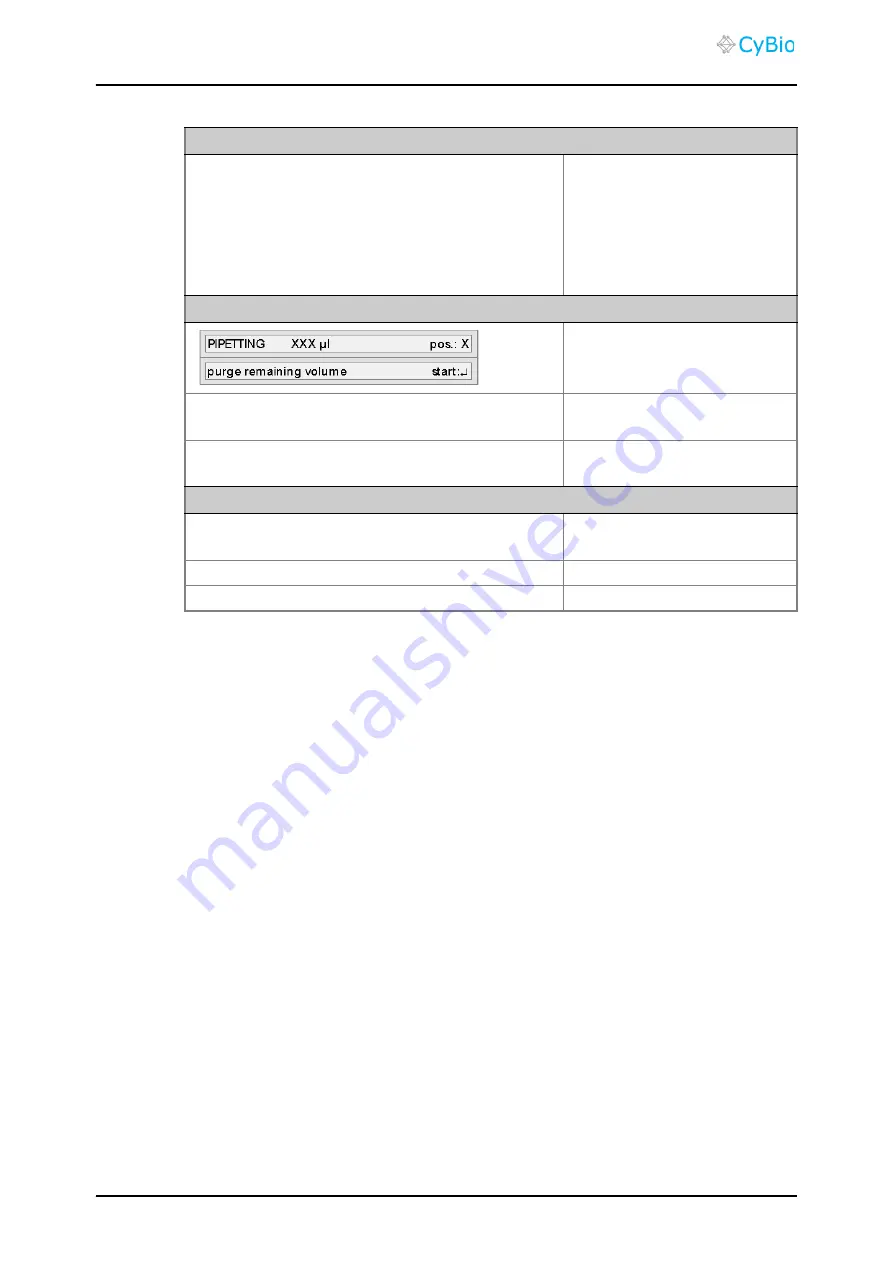
Trigger residual discharge
Confirmation:
input
key
Differential
amount
of
discharged
volume
and
as-
pirated
volume
is
discharged
The
lifter
moves
down
and
the
system
makes
a
break
for
dabbing.
Dabbing pause
Carriage
of
lifter
motion
in
order
to
facilitate
dab-
bing
Keys
,
,
and
Terminate
dabbing
pause
Confirmation:
input
key
Pistons
move
into
zero-position
Artisan Technology Group - Quality Instrumentation ... Guaranteed | (888) 88-SOURCE | www.artisantg.com