background image

AutoView 424 Installer/User Guide

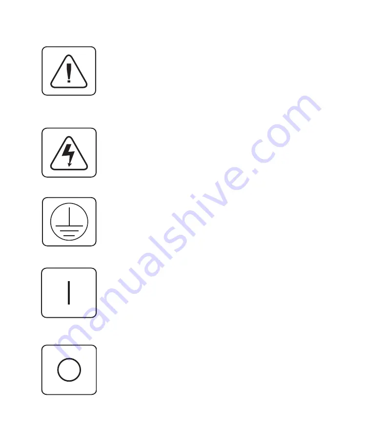
INSTRUCTIONS:

  The  exclamation  point  within  an  equilateral  tri-

angle is intended to alert the user to the presence of important oper-
ating and maintenance (servicing) instructions in the literature ac-
companying the appliance.

DANGEROUS VOLTAGE:

 The lightning flash with arrowhead sym-

bol, within an equilateral triangle, is intended to alert the user to the
presence  of  uninsulated  “dangerous  voltage”  within  the  product's
enclosure that may be of sufficient magnitude to constitute a risk of
electric shock to persons.

PROTECTIVE GROUNDING TERMINAL:

 A terminal which must be

connected to earth ground prior to making any other connections to
the equipment.

POWER ON:

 This symbol indicates the principal on/off switch is in

the on position.

POWER OFF:

 This symbol indicates the principal on/off switch is in

the off position.

Summary of Contents for AV416

Page 1: ...orted by 4991 Corporate Drive Huntsville Alabama 35805 6201 USA 256 430 4000 Fax 256 430 4030 www cybex com E mail Sales RackitTechnology com TM Technology Corporation 274 Madison Avenue New York NY 1...

Page 2: ...AutoView 424 Installer User Guide...

Page 3: ...Corporation Logitech and Kensington are registered trademarks of their respective companies MouseMan Marble and TrackMan are registered trademarks of Logitech Inc Cybex and the Cybex logo are register...

Page 4: ...alled and used in accordance with the instruction manual may cause harmful interference to radio communications Operation of this equipment in a residential area is likely to cause harmful interferenc...

Page 5: ...D Troubleshooting 41 E Problem Report 45 Chapter 6 Channel Scanning Choosing a Scanning Method 33 Turning Scanning On and Off 34 Scanning by List 35 Chapter 2 Installation Basic Install 5 Advanced In...

Page 6: ...n an equilateral triangle is intended to alert the user to the presence of uninsulated dangerous voltage within the product s enclosure that may be of sufficient magnitude to constitute a risk of elec...

Page 7: ...most Within the base unit AutoView 424 performs as a complete 2 x 24 matrix switch with both users independently accessing any of the 24 attached PCs at the same time Configure and control your AutoV...

Page 8: ...the event of an AutoView 424 power failure This prevents attached computers from locking up and keeps you from losing time and data The OSD Configuration Utility allows the administrator to easily con...

Page 9: ...A XGA II support Product Overview The AutoView 424 is also available in a 16 port version known as the AutoView 416 Aside from the number of ports all information in this manual that applies to the Au...

Page 10: ...AutoView 424 Installer User Guide...

Page 11: ...f your AutoView 424 For SUN support plug your Sun connector into the port labeled SUN for PS 2 peripherals plug your PS 2 keyboard cable and your PS 2 mouse cable into the ports labeled and respective...

Page 12: ...EIA TIA 568 B standard commonly used for 10BaseT Ethernet 4 Route the Category 5 cable to the location where you intend to place the secondary monitor keyboard and mouse 5 If you are using Remote PS 2...

Page 13: ...is now lit If you are using Remote Sun peripherals This will require a VAK 1 adaptor kit available from Cybex If your monitor uses a 13W3 plug connect the 15HDD male adapter to the port of your LongV...

Page 14: ...0 PS 2 only VGA 30 ft CUSBM 4 USB VGA 4 ft CUSBM 8 USB VGA 8 ft CUSBM 12 USB VGA 12 ft CWSNM 4 SUN Kbd Mouse 13W3 4 ft CWSNM 8 SUN Kbd Mouse 13W3 8 ft CWSNM 15 SUN Kbd Mouse 13W3 15 ft CWSNM 30 SUN Kb...

Page 15: ...y numbered channel port on the rear of the AutoView 424 The other end of the input cable will have up to three connectors depending on type Plug these connectors into the matching ports on your comput...

Page 16: ...s Sun peripherals you will need to configure the AutoView 424 to recognize them before they can be used To do this a At the local user activate the on screen display OSD by pressing either of the keyb...

Page 17: ...on the other end of the cable into the port labeled on your first cascading AutoView 424 unit Plug the PS 2 mouse connector into the port Plug the remaining 6 pin miniDIN keyboard connector into the...

Page 18: ...AutoView 424 Installer User Guide...

Page 19: ...security see the Administrator Functions section of chapter 4 Computers may be powered up one at a time or all at once No operator intervention is required during booting A computer may now be selecte...

Page 20: ...key Note For alternate hot key sequences see System Control Maintenance later in this chapter Enter Press the Enter or Return key The Enter command is used to execute an instruction and exit from Comm...

Page 21: ...ystrokes entered will be forwarded to the attached computer until you exit Command Mode Next enter the address Addr for the channel you wish to select Press Enter to accept the new channel The followi...

Page 22: ...your AutoView 424 CM SG Enter Enables the scan Go command By address only CM SH Enter Enables the scan Halt command CM M Enter Enables mouse suspension of scanning CM M Enter Disables mouse suspensio...

Page 23: ...login as Admin Root or Administrator Type your password and pressEnter This will bring up your Channel List If there is no keyboard activity the login window will timeout after five minutes and go bl...

Page 24: ...your up and down arrow keys and the page up and down keys to select a channel Move immediately to the top or bottom of the list with the home and end keys Press a letter while in the main OSD Window...

Page 25: ...signal while using the AutoView 424 select the Reset PS 2 Standard Mse Kbd option from this menu for a PC with a standard mouse driver or Reset PS 2 Wheel Mse Kbd if you are using a PC with a Microsof...

Page 26: ...Please note that the address cannot be longer than two digits For cascaded addresses see Keyboard Switching in Chapter 3 3 Enter the dwell time for the ID Window and press Enter 4 Enter the dwell tim...

Page 27: ...indow where you would like it to appear when this channel is selected Then press Enter For further information see The ID Window later in this chapter 6 Select Save Changes and press Enter to accept P...

Page 28: ...ss F3 skip Step 3 2 Select Edit Channel from the Command Menu 3 Choose the option ID Setup Follow the procedures outlined in the table below to change the size color or position of your ID Window The...

Page 29: ...main OSD Window 2 From the main OSD Window press the Control key twice to access the Administrator Command Menu 3 Select Edit Channel from the Command Menu 4 Choose the option ID Dwell Time 5 Enter a...

Page 30: ...menu your system will then be in secure mode A lock symbol will appear to the right of the menu headings to indicate secure operation Logout Capability You have the option of automatically logging ou...

Page 31: ...N Security is enabled once the password has been created Store a copy of your password in a safe place You should now see the option F10 Logout at the bottom of your main OSD Window and a lock symbol...

Page 32: ...ipherals that are appropriate to your remote setup Switch Selection Depending on your particular installation you may not want unpowered computers to be accessible If Switch Selection is toggled to Al...

Page 33: ...4 system just as if he were sitting in front of it Within the base unit there are two ways to utilize the multiuser capabilities of the AutoView 424 You can access computers independently or share acc...

Page 34: ...erent different different different AutoView 424 unit Shared Access If both users need to access the same computer in the base unit they can share access to it through the AutoView 424 Sharing means t...

Page 35: ...of the base unit the other user can be independently using computers 2 or 3 of the base unit or any computer attached to units 2 or 3 If one user is working on channel 2 of unit 2 the other user can b...

Page 36: ...he STOP and AGAIN keys that are on a true Sun keyboard But by turning Scroll Lock on the F1 and F2 keys on the PS 2 keyboard function as the Sun STOP and AGAIN keys With Scroll Lock off F1 and F2 func...

Page 37: ...g mode To issue the Power Sleep command to a PS 2 computer type Scroll Lock F11 or Sleep key For a Sun computer use the Power key 31 Advanced Operation Peripheral Keyboard On Shift F11 Scroll Lock Com...

Page 38: ...AutoView 424 Installer User Guide...

Page 39: ...AutoView 424 only scans the computers that are in your OSD list Scanning by address allows you to view each of your active channels in the order that they are attached to the AutoView 424 Scanning by...

Page 40: ...nd Menu 2 Select Scanning is OFF Scanning by Name Scanning by Address or Scanning by List from the menu This is a toggle option only one scanning option will show on the menu at any one time Selecting...

Page 41: ...t menu where you can add or delete users from your custom scan list CYBEX Control Panel Administrator Scan List Address Enter Save Esc Cancel Dwell Name 1 5 Kyle 2 5 Pam 3 5 John 4 5 Charlene F2 Add F...

Page 42: ...AutoView 424 Installer User Guide...

Page 43: ...orted Hardware Computer IBM PC AT PS 2 Sun workstations USB computers and 100 compatibles Video Modes VGA SVGA XGA XGA II with adaptor Maximum Resolution 1600 x 1200 85 Hz Peripherals PS 2 keyboard PS...

Page 44: ...ongView Specifications Mechanical Height 1 9 4 8 cm Width 8 1 20 6 cm Depth 4 8 12 2 cm Weight 1 lb 0 45 kg Environmental Operating Temperature 5 C to 40 C Power Storage Temperature 20 C to 50 C Power...

Page 45: ...onics stores to connect a computer to your AutoView 424 Simply connect the serial cable between the SETUP port on your AutoView 424 to the serial port on the computer You will next need some form of t...

Page 46: ...n to continue You must type out the word Yes before proceding Once you have done this the AutoView 424 will go into a standby mode and wait for data from the computer Note The keyboard video and mouse...

Page 47: ...ned on Check power cable If the problem persists contact Cybex Technical Support Unable to hot key switch to Check the power indicator on the OSD screen to ensure a channel that the system in question...

Page 48: ...e correct PS 2 computer channels port on the back of the AutoView 424 Try the mouse reset command MR or try the Reset PS 2 Standard Mse Kbd command from the OSD Command Menu for computers using PS 2 m...

Page 49: ...and try again If the problem persists contact Cybex Technical Support Keyboard is inoperable after If you are operating in secure mode verify your switching channels keyboard and mouse privileges If t...

Page 50: ...are on the same phase Best results are obtained when they are on the same circuit Use only Cybex supplied cable Cybex warranties do not apply to damage resulting from user supplied cable Do not use a...

Page 51: ...to Technical Support directly Company Name Contact Name Phone Number Fax Number Service Call Number if one has been issued AutoView 424 Part Serial Revision Name and Model of Monitor Name and Model of...

Page 52: ...r attached to your AutoView 424 system Problem Description Include all affected ports exact nature of problem troubleshooting steps taken etc Port Computer Manufacturer Model BIOS Manufacturer Revisio...

Page 53: ......

Page 54: ...AutoView 424 Installer User Guide...

Page 55: ...ng can diminish video quality and damage equip ment Cybex manufactured cabling is built to high quality standards utilizing overall braided shield to comply with FCC emission standards and each cable...

Page 56: ...Asia Pacific Singapore Representative Office 19 B Bukit Pasoh Road Singapore 089833 Tel 0065 223 9198 Fax 0065 223 9155 E mail info asiapac cybex ie Cybex Germany Dachauerstrasse 44a 80335 Munchen Ge...

Reviews: