


DEFINITIONS FOR ILLUMINATED LCD INDICATORS
TROUBLESHOOTING
TECHNICAL SPECIFICATIONS
1 . ONLINE:
The UPS is supplying utility power to connected equipment.
2 . ENERGY-SAVING:
The UPS in energy-saving bypass mode. See “CyberPower
GreenPower UPS™ Technology” section for more information.
3 . AVR (Automatic Voltage Regulation):
This icon appears whenever your UPS is
automatically correcting low AC line voltage without using battery power. This is a
normal, automatic operation of your UPS, and no action is required on your part.
4 . ON BATTERY:
During a loss in power or severe sag, this icon appears and an alarm
sounds (two short beeps followed by a pause) to indicate the UPS is operating from its
internal batteries. During a prolonged loss in power, the alarm will beep rapidly every
1/2 second to indicate the UPS’s batteries are nearly out of power. You should save
files and turn off your equipment immediately or allow the software to shut the system
down.
5 . BATTERY CAPACITY:
This meter displays the approximate charge level (in 20%
increments) of the UPS’s internal battery. During a loss in power or severe sag the UPS
switches to battery power, the BATTERY icon appears, and the charge level decreases.
6 . REPLACE BATTERY:
This icon illuminates when the batteries are not connected well
or the batteries were worn out.
7 . FAULT:
This icon appears if there is a problem with the UPS. Press the POWER button
to turn the UPS off.
E01 :
Charger Fault – Overcharge (Contact CyberPower Systems for support.)
E02 :
Charger Fault – No Charge (Contact CyberPower Systems for support.)
E11 :
Battery Overvoltage (Contact CyberPower Systems for support.)
E21 :
Output Short (Check the status of equipment connected to the UPS and then
turn on the UPS again.)
E22 :
Overload (Unplug at least one piece of equipment from battery outlets and turn
the UPS on again.)
8 . OVERLOAD:
This icon appears and an alarm sounds to indicate the battery-supplied
outlets are overloaded. To clear the overload, unplug one piece of equipment from the
battery-supplied outlets at a time until the icon turns off and the alarm stops.
9 . CURRENT LOAD:
This meter displays the approximate output load level (in 20%
increments) of the UPS battery outlets.
10
. SCHEDULE:
Users can setup the schedule to turn on and shut down the computer and
UPS through PowerPanel® Personal software. The LCD display will show how much
time is left before the UPS will turn back on or shut down.
11 . MUTE:
This icon appears whenever the UPS is in silent mode. However, when there is a
problem with the UPS, the alarm will still beep even in silent mode.
12 . SENSITIVITY SETUP:
This meter is also used to setup the UPS sensitivity when you
are in the programming mode. If the connected equipment can tolerate more power
events (example: unstable power often associated with stormy weather), select Low
Sensitivity and the UPS will go to Battery Mode less often. If the connected equipment
is more sensitive to power events, select High Sensitivity and the UPS will go to
Battery Mode more often.
13 . ESTIMATED RUNTIME:
This displays the runtime estimate of the UPS with current
battery capacity and load.
14 . OUTPUT METER:
This meter measure, in real time, the AC voltage that the UPS system
is providing to the computer, such as normal AC line mode, AVR mode, and battery
backup mode. (Note: The OUTPUT meter shows the status of the battery backup
outlets in terms of load, frequency, and voltage.)
15 . EVENT:
This meter records the number of power outages.
16 . INPUT METER:
This meter measures the AC voltage that the UPS system is receiving
from the utility wall outlet. The INPUT voltage meter can be used as a diagnostic tool
to identify poor-quality input power.
For more information about functions setup, please refer to the Function Setup Guide.
Problem
Possible Cause
Solution
Circuit breaker button is projecting from the back of
the unit.
Circuit breaker has tripped due to an overload.
Turn the UPS off and unplug at least one piece of equipment.
Wait 10 seconds, reset the circuit breaker by depressing the
button, and then turn the UPS on.
The UPS does not perform expected runtime.
Battery not fully charged.
Recharge the battery by leaving the UPS plugged in.
Battery is worn out.
Contact CyberPower about replacement batteries.
The UPS will not turn on.
The on/off switch is designed to prevent damage from
rapidly turning it off and on.
Turn the UPS off. Wait 10 seconds and then turn the UPS on.
The unit is not connected to an AC outlet.
The unit must be connected to a 110/120V 60Hz outlet.
The battery is worn out.
Contact CyberPower about replacement batteries.
Mechanical problem.
Contact CyberPower.
PowerPanel® Personal software is inactive
(all icons are gray).
The USB / serial cable is not connected.
Connect the USB / serial cable to the UPS unit and an open USB
/ serial port on the back of the computer.
The USB / serial cable is connected to the wrong port.
Check the back of the computer for an additional USB / serial
port. Move the cable to this port.
The unit is not providing battery power.
Shutdown your computer and turn the UPS off. Wait 10 seconds
and turn the UPS back on. This should reset the unit.
The USB charging ports are not providing power to the
connected devices.
The USB power port has Over Current Protection design.
When the total current of connected devices is over 4 A,
the USB charging ports will stop providing power to the
connected devices.
Turn the UPS off and unplug at least one piece of device
connected to the USB charging port and then turn the UPS on.
Additional troubleshooting information can be found under “Support” at www.CyberPowerSystems.com.
Model
LX1100G3
-FC
LX1325GU3
-FC
LX1500GU3
-FC
Capacity
1100VA / 660W
1325VA / 810W
1500VA / 900W
Nominal Input Voltage
120V
Input Frequency
60 Hz ± 3 Hz
On-Battery Output Voltage
120Vac ± 5%
Max. Load for UPS Outlets (5 Outlets)
1100VA / 660W
1325VA / 810W
1500VA / 900W
Max. Load for Full-Time Surge Protection
outlets (10 Outlets)
12 Amp
On-Battery Output Wave Form
Simulated Sine Wave
Operating Temperature
+ 32°F to 104° F / 0° C to 40° C
Operating Relative Humidity
0 to 90% non-condensing
Size (W x H x D)
3.9" x 9.8" x 13.7" (99 x 249 x 348 mm)
Net Weight
21.8lbs / 9.9kg
22.2lbs / 10.1kg
25lbs / 11.3kg
Battery Type
CyberPower / RB1270X2C
CyberPower / RB1270X2C
CyberPower / RB1290X2
Typical Battery Recharge Time
8 hours to 90% capacity from total discharge
Typical Battery Life
3 to 6 years, depending on number of discharge/recharge cycles
Recommended Battery
Sealed Maintenance Free Lead Acid Battery
Safety Approvals
UL1778 (UPS), CSA C22.2 No. 107, FCC/DoC Class B
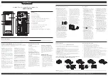
SYSTEM BLOCK DIAGRAM
Input
Output
EMI Fllter
Surge
Suppressor
AVR
Charger
AC / DC
Battery
Inverter
Normal Mode
Battery Mode
This device complies with part 15 of the FCC rules. Operation is subject to the
following two conditions: (1) this device may not cause harmful interference,
and (2) this device must accept any interference received, including
interference that may cause undesired operation.
Note:
This equipment has been tested and found to comply with the limits for a Class B
digital device, pursuant to part 15 of the FCC Rules. These limits are designed to provide
reasonable protection against harmful interference in a residential installation. This
equipment generates, uses, and can radiate radio frequency energy and, if not installed
and used in accordance with the instructions, may cause harmful interference to radio
communications. However, there is no guarantee that interference will not occur in a
particular installation. If this equipment does cause harmful interference to radio or
television reception, which can be determined by turning the equipment off and on, the user
is encouraged to try to correct the interference by one or more of the following measures:
FCC COMPLIANCE STATEMENT
- Reorient or relocate the receiving antenna.
- Increase the separation between the equipment and receiver.
- Connect the equipment to an outlet on a circuit different from that to which the receiver is
connected.
- Consult the dealer or an experienced radio/TV technician for help.
Important: Changes or modifications not expressly approved by the party responsible for
compliance could void the user's authority to operate the equipment.
Canadian Compliance Statement
CAN ICES-3 (B)/NMB-3(B)
FCC COMPLIANCE STATEMENT - Continued
CYBERPOWER GREENPOWER UPS™ TECHNOLOGY
Advanced Energy-Saving Patented Bypass Technology
CyberPower’s patented GreenPower UPS™ with Bypass Technology
reduces UPS energy costs by up to 75% compared to conventional UPS
models. Even when utility power is normal, conventional UPS models
constantly pass power through a transformer. By contrast, under normal
conditions the advanced circuitry of a GreenPower UPS™ bypasses the
transformer. As a result, the power efficiency is significantly increased
while decreasing waste heat, using less energy, and reducing energy costs.
When an abnormal power condition occurs, the GreenPower UPS™ automatically runs power
through its transformer to regulate voltage and provide “safe” power. Since utility power is
normal over 88% of the time, the GreenPower UPS™ operates primarily in its efficient bypass
mode.
The GreenPower UPS™ is also manufactured in accordance with the Restriction on
Hazardous Substances (RoHS) directive making it one of the most environmentally-friendly
on the market today.
G
REEN
P
OWER
UPS
™
Energy-Saving Technology
LIMITED WARRANTY AND CONNECTED EQUIPMENT GUARANTEE
Please visit www.CyberPowerSystems.com for a copy of the Limited Warranty and
Connected Equipment Guarantee.
Where Can I Get More Information?
The application of the United Nations Convention of Contracts for the International Sale of
Goods is expressly excluded. CyberPower is the warrantor under this Limited Warranty.
For further information please feel free to contact CyberPower at:
Cyber Power Systems (USA), Inc.
4241 12th Ave E., STE 400, Shakopee, MN 55379;
Call us at
(877) 297-6937
; or
submit a web ticket online at
cyberpowersystems.com/support.
WARNING:
This product can expose you to chemicals including bisphenol A (BPA) and
styrene, which is known to the State of California to cause reproductive harm and cancer.
For more information, go to www.P65Warnings.ca.gov.
CyberPowerSystems.com
© 2021 Cyber Power Systems (USA), Inc. PowerPanel® Personal is a trademark of Cyber
Power Systems (USA) Inc.
All rights reserved. All other trademarks are the property of their respective owners.
DISPLAY
3
7
11
10
12
13
14
15
16
1
9
8
4
5
6
2