background image

 CPS725SL 

Guaranteed Uninterruptible Power System 


7.  Disconnect the battery wires from the battery. 
8.  Install the replacement battery by connecting the red wire to the positive (+) terminal of the battery and connecting 

the black wire to the negative (-) terminal of the battery. 

9.  Slide the battery back into the compartment. 
10.  Replace the outlet cover and the 6 retaining screws. 
11.  Recharge the unit for 4 – 8 hours to ensure the UPS performs expected runtime. 

REMINDER:  

Batteries are consider 

HAZARDOUS WASTE

 and must be disposed of properly.  Contact your 

local government for more information about proper disposal and recycling of batteries. 


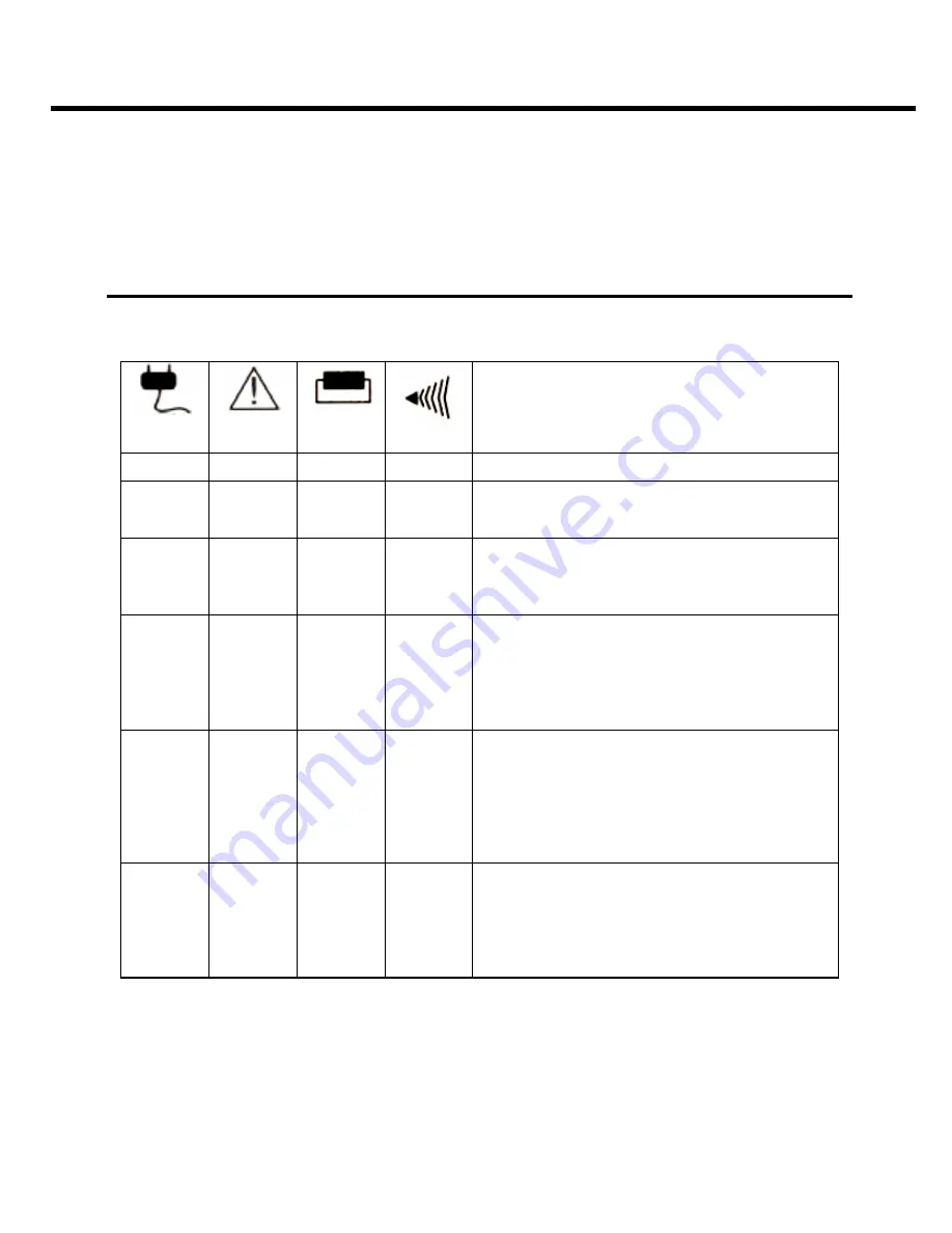
DEFINITIONS FOR ILLUMINATED LED INDICATORS 


Power 

ON 


Wiring 

Fault 


Circuit 

Breaker 


Alarm 

CONDITION 

On Off Set Off 

Normal 

Off On/Off Set 

Two 

Beeps 

Utility Failure- 

the UPS is providing power to 

battery power-supplied outlets from its battery. 
 

Off On/Off Set 

Rapid 

Beeps 

Utility Failure-

 The UPS is providing battery 

power.  Rapid beeps indicate the unit will run 
out of power shortly. 
 

Off Off Up 

Two 

Beeps 

or        

Rapid 

Beeps 


System Overload- 

Occurs when connected 

equipment exceeds the rating of unit.  Turn the 
UPS off, unplug at least one piece of equip-
ment, wait 10 seconds, reset the circuit 
breaker and turn the unit on. 

Off On/Off Set 

Long 
Beep 

Battery Overload-

 Occurs when connected 

equipment exceeds the rating of battery out-
lets of the unit.  Turn the UPS off, unplug at 
least one piece of equipment from battery 
outlets, wait 10 seconds, reset the circuit 
breaker and turn the unit on. 
 

On/Off On  Set  None 

Electrical Wiring Fault- 

This 

indicates a 

wiring problem with the AC outlet

 such as 

bad ground, miss ground, or reversed wiring.  
User is advised to disconnect all electrical 
equipment from the outlet and have an electri-
cian check the outlet to insure proper wiring. 

Summary of Contents for CPS725SL

Page 1: ...User s Manual for CPS725SL with USB Interface and PowerPanel Software ADDITIONAL INSTALLATION TIPS CAN BE FOUND AT www cyberpowersystems com FAQs htm...

Page 2: ...operation instructions completely This UPS is designed to provide guaranteed power protection for connected electronic equipment The accompanying PowerPanel software saves data closes open applicatio...

Page 3: ...nsures temporary uninterrupted operation of your equipment during a power failure 2 Full Time Surge Protection Outlets Provides three always on surge suppression outlets 3 Power Switch Can be used as...

Page 4: ...lied outlets Plug your peripheral equipment printer scanner speakers into the full time surge protection outlets DO NOT plug a laser printer copier space heater vacuum or other large electrical device...

Page 5: ...was supplied with the unit 3 Plug the UPS into an AC outlet turn the UPS on and start your computer 4 Once the computer was finished booting insert the PowerPanel disk into the floppy drive 5 Click on...

Page 6: ...tton to open the Scheduled Shutdown Window 6 AC Power Indicator This indicator appears in a green color when AC power in normal When the power fails the indicator will change to a red color with an X...

Page 7: ...utton to add the item to the schedule Please note The use of the schedule is optional and will have no effect on the shutdown of your system during a power failure This feature is simply used if you w...

Page 8: ...lure 3 The UPS will begin beeping indicating a power failure 4 Save and close any open files 5 Shut down the operating system 6 Once the computer system is shutdown turn the UPS off As the battery dis...

Page 9: ...he UPS is providing power to battery power supplied outlets from its battery Off On Off Set Rapid Beeps Utility Failure The UPS is providing battery power Rapid beeps indicate the unit will run out of...

Page 10: ...e battery is worn out Contact CyberPower Systems about replacement batteries at tech cyberpowersystems com The UPS will not turn on Mechanical problem Contact CyberPower Systems at tech cyberpowersyst...

Page 11: ...F 0 C to 35 C Operating Relative Humidity 0 to 95 NON CONDENSING Size Length x Width x Height 9 7 8 x 6 3 16 x 3 1 8 25 8cm x 15 9cm x 8 3cm Net Weight 15 lbs Typical Battery Re charge Time 8 hours t...

Page 12: ...by and become a party to the Limited Warranty and Power Control Guarantee If you do not agree to the terms and conditions of the Limited Warranty and Power Control Guar antee you should return the Pr...

Page 13: ...rage whether or not the Initial Customer makes a claim for recovery includ ing but not limited to a claim under any applicable insurance other warranty or extended warranty The Limited Warranty does n...

Page 14: ...Agreed Damage Amount for all items of Initial Customer s Connected Equipment shall be the lesser of the amount determined under Clause 1 or 2 below reduced by any amounts described in Clause 3 below 1...

Page 15: ...ibed as excluded above with respect to the product 4 Damages from fire flood wind rain rising water leakage or breakage of plumbing abuse misuse or alteration of either the product or the Connected Eq...

Page 16: ...s 5555 12th Ave East Suite 110 Shakopee MN 55379 and its phone number is 952 403 9500 or 877 297 6937 toll free CyberPower is the warrantor under this Limited Warranty You may also contact CyberPower...

Page 17: ...uipment into an outlet on a circuit different from that to which the receiver is connected 4 Consult the dealer or an experienced radio TV technician for help Any special accessories needed for compli...

Reviews: