


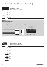


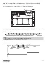


3.5 Pinout (model with interconnection module)
1
2
3
4
5
POWER SUPPLY
Tripolar female connector
J2
1 GND
2 +VRE
3 GND
4 Frame GND
5 Frame GND
ATTENTION:
Respect power supply polarity .
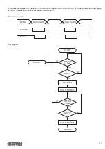
NOTE: Power supply cable
The following figure shows the connector pinout of the power supply cable for the device:
Tripolar male connector
+24 V
n.c.
GND
Power supply cable
1
2
3 4
USB INTERFACE
Female USB type B connector
J5
1 VPLUG
(in)
2 D0-
(in/out)
3 D0+
(in/out)
4 GND
SH1 GND
SH2 GND
24
Summary of Contents for PLUS4
Page 1: ...USER MANUAL PLUS4 ...
Page 2: ......
Page 4: ......
Page 5: ...MANUAL For details on the commands refer to the manual with code 77200000002100 ...
Page 6: ......
Page 10: ...10 ...
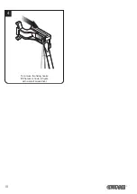
Page 18: ...4 To remove the fixing hooks lift the lever shown in figure with a small screwdriver 18 ...
Page 36: ...36 ...
Page 50: ...50 ...
Page 60: ...60 ...