


STEP 3. INSTALL THE BREW HEAD
CAUTION:
Do not open the brew head units! The length of the wires and tubing are fixed and set at the factory. Do not
splice or extend the tubes that come from beneath the brew head assembly. Ample tube length is provided and the tubes
will need to be shortened in most cases for proper installation.
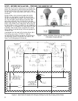
Install the brew head units into the counter top in the correct position. One brew head is designed to be installed on the right side
and the other on the left. The installation position for each brew head is marked on the attached wires and tubes. Each brew head
has three 1/4–20 studs with matching nuts and washers for mounting onto the surface of the counter. Hold a brew head over the
group of holes that matches the markings on the brew head tubing/wiring (right or left). Insert the tubes and wires into the large
center hole and insert the studs through the three smaller holes, while pushing the unit down onto the counter top. Secure with the
nuts supplied. Repeat for the other brew head.
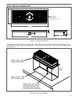
STEP 4. INSTALL THE UCM ASSEMBLY
Locate the wiring harness and UCM plugs coming from
behind the water tower. Plug the touch screen wiring
harness and USB wiring into the receptacles in back of
the UCM. These will snap and lock into place. Install the
UCM/holder onto the counter top. Slip the two 1/4–20
threaded studs into the counter top and fasten the holder
to the Counter using (1) fender washer, (1) lock washer
and (1) nut per threaded stud. Once the touchscreen and
the brew head assemblies are properly installed in the
counter top, proceed to the next step.
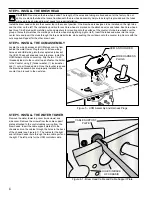
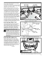
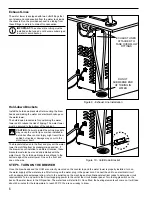
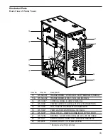
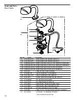
STEP 5. INSTALL THE WATER TOWER
Remove the water tower top cover (two screws) and
side cover. Remove the screws from the cable support
plates, attached to the control cables coming from the
brew heads. Insert the cable support plates into the
chassis and run the cables through the holes in the back
of the chassis (see Figure 6.1). The cables for the right
and left brew heads route through the two cable ports on
the right. The left port is for the UCM controller cable.
Figure 5 - UCM Assembly and Harness Plugs
Figure 6.1 - Brew Head Cable and Cable Support Plate
UCM AND HOLDER
WIRE HARNESS
PLUGS
CABLE SUPPORT
PLATE
HOLES IN BACK
OF CHASSIS
4


