Curtis Instruments MultiMode 1230 Manual Download Page 43

Curtis 1230 Manual, 

Rev. C

37

3 — PROGRAMMABLE PARAMETERS: 

Motor Control Parameters
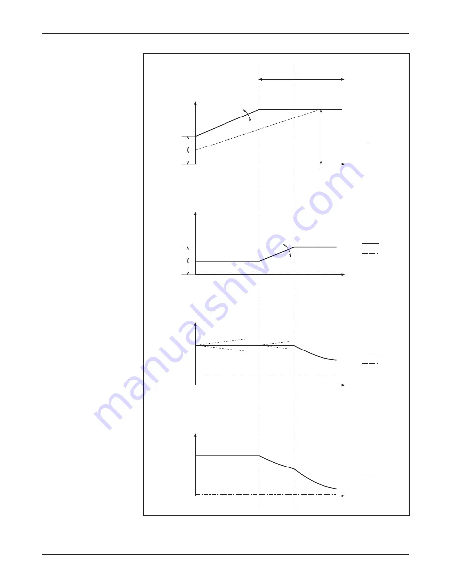
Fig. 16

  Motor control pa-

rameters and their effect on 
operating characteristics. 

HIGH SPEED

CONSTANT TORQUE

CONSTANT

POWER

MOTOR

VOLTAGE

(rms)

FREQUENCY

Field  Weakening

Accel Slip Voltage

Min Motor Voltage

+

-

Accel Compensation

Nominal Motor 

Vo

lta

ge

Nominal

Motor

Frequency

Full Load

No Load

SLIP

FREQUENCY

(Hz)

FREQUENCY

Pull Out Slip

Accel Slip

+

-

Slip Boost

Full Load

No Load

MOTOR

CURRENT

(rms)

FREQUENCY

Slip Boost:

Full Load

No Load

TORQUE

FREQUENCY

Full Load

No Load

Accel Compensation:

too high

too low

too high

too low

Summary of Contents for MultiMode 1230

Page 1: ...S INC DESIGN OF CURTIS 1200 SERIES CONTROLLERS PROTECTED BY U S PATENT NO 4626750 1230 M O D E L MultiMode AC INDUCTION MOTOR CONTROLLER CURTIS INSTRUMENTS INC 200 Kisco Avenue Mt Kisco New York 10549 USA Tel 914 666 2971 Fax 914 666 2188 www curtisinstruments com ...

Page 2: ......

Page 3: ... wire resistive throttle Type 3 17 Wigwag 0 5V and 3 wire pot throttles Type 4 17 Three step switch throttle Type 5 18 Wiring Auxiliary Drivers 18 Wiring Emergency Reverse 18 Wiring Emergency Reverse Check 19 Wiring Spyglass Display 19 Wiring Tiller Multiplexer 20 Contactor Switches and Other Hardware 20 3 PROGRAMMABLE PARAMETERS 23 Vehicle Parameters Rate Parameters 25 Acceleration Rate Decelerat...

Page 4: ... Motor Frequency Max Motor Speed Number of Motor Poles Encoder Pulses Per Revolution Swap Encoder Direction Failsafe Delay Control Parameters 36 P Gain I Gain Accel Slip Regen Slip Slip Boost Pull Out Slip Accel Slip Voltage Regen Slip Voltage Accel Comp Regen Comp Regen Voltage Offset System Parameters Battery Parameters 38 Full Battery Voltage Empty Battery Voltage BDI Reset Battery Voltage Batt...

Page 5: ...hrottle Max Hyd Throttle Map Max Pump Run Time Other System Parameters 43 Power Save Delay Mux Inputs Enabled Inhibit Input Type Auxiliary Output Type Fault Code Controller Cloning 44 4 MONITOR MENU 45 5 INITIAL SETUP 46 6 VEHICLE PERFORMANCE ADJUSTMENT 51 7 DIAGNOSTICS AND TROUBLESHOOTING 54 LED Diagnostics 54 Spyglass Diagnostics 55 Programmer Diagnostics 55 Troubleshooting Chart 55 8 MAINTENANC...

Page 6: ... 3 17 FIG 11 Wiring for wigwag 3 wire potentiometer Type 4 17 FIG 12 Wiring guide and mounting dimensions Curtis 840 Spyglass display 19 FIG 13 Wiring guide and mounting dimensions Curtis 1312 Multiplexer 20 FIG 14 Influence of various parameters on controller output response to throttle demand 29 FIG 15 Overview of motor control 34 FIG 16 Motor control parameters and their effect on operating cha...

Page 7: ...AC motor controller The 1230 controller offers smooth precise control of motor speed and torque When used with hydraulic systems the 1230 turns the pump motor on and off and also controls valves on the hydraulic line thus controlling the hydraulic path for Lift and Lower operations These controllers are fully programmable through Curtis s optional 1311 handheld programmer or 1314 PC programming st...

Page 8: ...r associ ated maintenance timers are built into the controller with EEPROM storage no battery BDI calculations performed within controller Meets EEC fault detection requirements Fault detection circuitry on throttle inputs can be used to inhibit operation if throttle signal goes out of range for any reason applies both to the traction throttle and in applications that include a proportional valve ...

Page 9: ...lass Display 3 wire serial interface Sequences between hourmeter BDI and error displays Alphanumeric 8 character 5 mm LCD display for hourmeter BDI and fault messages Operating temperature range 10 C to 70 C models with lower temperature ratings available for freezer applications Curtis Model 1312 Tiller Multiplexer 4 wire serial interface increases reliability Multiplexes up to 12 signals analog ...

Page 10: ...n 1 that the built in Status LED is visible only through the view port in the label on top of the controller and 2 that convenient access is needed at the top of the controller to plug the programmer into its connector The outline and mounting hole dimensions for the 1230 controller are shown in Figure 2 To ensure full rated power the controller should be fastened to a clean flat metal surface with...

Page 11: ...cuit before working on the motor control circuit Wear safety glasses and use properly insulated tools to prevent shorts LEAD ACID BATTERIES Charging or discharging generates hydrogen gas which can build up in and around the batteries Follow the battery manufacturer s safety recommendations Wear safety glasses holes provided Although not usually necessary a thermal joint compound can be used to imp...

Page 12: ...nput KSI J1 Pin 2 interlock J1 Pin 3 mode switch input M1 open M2 closed J1 Pin 4 inhibit input J1 Pin 5 pot high output J1 Pin 6 wiper 0 5V input for throttle J1 Pin 7 pot low input J1 Pin 8 not used J1 Pin 9 feed through ground J1 Pin 10 speed limit input J1 Pin 11 feed through input 1 J1 Pin 12 feed through input 2 J1 Pin 13 forward switch input J1 Pin 14 reverse switch input J1 Pin 15 emergenc...

Page 13: ...anual for further information on the various programmers available for programming Curtis controllers J3 can also be used for the Curtis Model 840 Spyglass display Although the display is typically wired directly into Pins 19 20 and 21 of the 24 pin connector J1 it can alternatively be plugged into J3 and unplugged when the programmer is used Only Pins 2 3 and 4 of J3 are needed for the display Hi...

Page 14: ...A Enc B Enc Ground Brake Brake Return Feed thru 1 Feed thru 2 Aux Ground Main Contactor B 1230 2X02 CONTROLLER Feed thru 2 J1 12 Lower Inhibit J1 4 Inhibit Emerg Rev Check J1 16 Emergency Reverse J1 15 Mode M1 M2 J1 3 Reverse J1 14 Forward J1 13 Forward Interlock J1 2 KSI J1 1 Prog Supply J3 4 Prog Receive J3 1 Prog Transmit J3 3 Prog Ground J3 2 Pot High J1 5 Speed Limit J1 10 Throttle Wiper J1 6...

Page 15: ...ctly to the B stud The positive battery terminal is typically connected to the F stud via the ex ternal main contactor as shown in Figure 3 If the main fuse in not mounted on the controller F is not used and the positive battery terminal is connected to the B stud If a main contactor is not required the positive battery terminal can be connected directly to the B or F stud on the controller Standa...

Page 16: ... Brake Brake Return Auxiliary Output 1 Auxiliary Output 2 B 1230 2X01 CONTROLLER Pot Low J1 7 Emerg Rev Check J1 16 Emergency Reverse J1 15 Mode M1 M2 J1 3 Reverse J1 14 Interlock J1 2 Battery LED Battery LED Status LED KSI J1 1 Prog Supply J3 4 Prog Receive J3 1 Prog Transmit J3 3 Prog Ground J3 2 AC MOTOR SPEED ENCODER J2 1 J2 2 J2 4 J2 5 J2 6 J2 3 E M Brake J1 23 Keyswitch BATTERY Status LED In...

Page 17: ...se connections will affect the operation of the emergency reverse feature The forward and reverse switches and the U V W connections must be configured so that the vehicle drives away from the operator when the emergency reverse button is pressed The negative battery terminal is always connected directly to the B stud The positive battery terminal is typically connected to the F stud as shown in Fi...

Page 18: ...V Return Auxiliary Output 1 Auxiliary Output 2 B Load Hold Valve 1230 2X01 CONTROLLER Pot Low J1 7 Emerg Rev Check J1 16 Emergency Reverse J1 15 Mode M1 M2 J1 3 Reverse J1 14 Interlock J1 2 Battery LED Battery LED Status LED KSI J1 1 Prog Supply J3 4 Prog Receive J3 1 Prog Transmit J3 3 Prog Ground J3 2 AC MOTOR SPEED ENCODER J2 1 J2 2 J2 4 J2 5 J2 6 J2 3 Proportional Valve J1 23 Keyswitch BATTERY...

Page 19: ...y reverse button is pressed The negative battery terminal is always connected directly to the B stud The positive battery terminal is typically connected to the F stud as shown in Figure 5 If the main fuse in not mounted on the controller F is not used and the positive battery terminal is connected to the B stud Standard Control Wiring Configuration C Wiring for the input switches and contactors is...

Page 20: ...les can be used with the 1230 controller They are categorized as one of five types in the programming menu of the 13XX programmer Only Types 2 and 4 can be used for the hydraulic throttle Type 1 two wire 5kΩ 0 potentiometer throttles Type 2 0 5V current source and three wire pot throttles wired for single ended operation Type 3 two wire 0 5kΩ potentiometer throttles Type 4 0 5V and three wire pot t...

Page 21: ...ype 2 With these throttles Type 2 in the programming menu the controller looks for a voltage signal at the wiper input Zero speed corresponds to 0 V and full speed to 5 V A variety of devices can be used with this throttle input type including voltage sources current sources and 3 wire pots The wiring for each is slightly different and each has varying levels of throttle fault protection associate...

Page 22: ...rottle must be used to convert the current source value to a voltage The resistor should be sized to provide a 0 5V signal variation over the full current range Fig 8 Wiring for current source throttle Type 2 R throttle I source B B 0 5V input Pin 6 It is the responsibility of the OEM to provide appropriate throttle fault detection for current sources used as throttles 3 Wire Pot Throttle 1 10 kΩ ...

Page 23: ...tral point for Type 4 throttles is with the wiper at 2 5 V measured between Pot Low Pin 6 and B Fig 10 Wiring for 0 5kΩ throttle Type 3 0 5kΩ Pot Low input Pin 7 Wiper input Pin 6 FASTER For the traction throttle the controller will provide increasing forward speed as its wiper input value Pin 4 is increased above the neutral point and increasing reverse speed as the wiper input value is decreased...

Page 24: ...SET Pin 6 Pin 10 FOR THIS PARAMETER Open Open Throttle Deadband Closed Open Throttle Map Closed Throttle Max WIRING Auxiliary Drivers 1230 2X01 MODELS ONLY Two auxiliary drivers are provided at Pins 23 and 24 These low side drivers depending on how they are programmed see page 43 can be used for a variety of functions Output is rated at 2 amps An active clamping circuit at 70 V provides fast turn ...

Page 25: ...ng If there is no continuity the controller output is inhibited until the wiring fault is corrected If the option is selected and the check wire is not connected the vehicle will not operate If the option is not selected and the check wire is connected no harm will occur but continuity will not be checked Emergency reverse checking is disabled if the emergency reverse input is configured to accept ...

Page 26: ...s are designed to work with open collector output quadrature encoders such as SKF sensorized bearings If you intend to use a different type of encoder or sensors please contact your local Curtis office Fig 13 Wiring guide and mounting dimensions for Curtis 1312 Multiplexer The 1312 provides four connectors J1 is a connector that can be used to inhibit the controller during battery charging J2 is no...

Page 27: ...river output to remove power from the controller and motor in the event of various other faults If the main contactor coil is not wired to J1 Pin 22 the controller will not be able to open the main contactor in serious fault conditions and the controller will not be protected against reverse battery polarity 1230 2001 2101 and 2201 models These models have an internal main contactor and therefore ...

Page 28: ...2 TheSpeedLimitTypeparameterconfiguresthespeed limit input The Min Speed parameter sets the maximum speed at full throttle when the speed pot wiper is shorted to the Pot Low connection Pin 7 or the speed limit switch is in the Min Speed position The Max Speed parameter sets the maximum speed at full throttle when the wiper is shorted to Pot High Pin 5 or the switch is in the Max Speed position Batt...

Page 29: ...gramming menu A complete list of the individual parameters is presented on the next page The parameters are described in the charts that follow For each parameter the charts provide parameter name as it appears in the programmer display allowable range description of the parameter s function and where applicable suggestions for setting it We urge you to read Section 5 Initial Setup before adjustin...

Page 30: ...es Encoder Pulses Revolution Swap Encoder Direction Failsafe Delay Control Parameters P Gain I Gain Accel Slip Regen Slip Slip Boost Pull Out Slip Accel Slip Voltage Regen Slip Voltage Accel Comp Regen Comp Regen Voltage Offset SYSTEM GROUP Battery Parameters Full Voltage Empty Voltage BDI Reset Battery Voltage Battery Recharge Level Low Voltage Level Hourmeter Parameters Enable Total Service Hour...

Page 31: ...ake Rate 0 1 5 0 sec Defines the time it takes the controller to brake from 100 output to 0 output when a new direction is selected Larger values represent a longer time and consequently gentler braking Faster braking can be achieved by adjusting the braking rate to a smaller value The Brake Rate should be set to a lower value faster deceleration than the corresponding Decel Rate Fast Stop Rate 0 1...

Page 32: ... calling for maximum speed Speed Limit Type 0 3 Configures the speed limit input to work with a speed limit pot analog input or with a switch either normally open or normally closed 0 no speed limit speed limit input is ignored 1 linear speed limit speed limit pot programmed max speed when speed limit input voltage 5 0 V programmed min speed when speed limit input voltage 0 2 V 2 normally open swit...

Page 33: ... Creep Same as 0 except that the transition from Mode 2 to Mode 1 is only possible when interlock is Off or throttle input is 0 Coast Decel Rate 0 1 20 0 sec Defines how quickly the controller reduces its output to zero when the throttle is released This parameter allows adjustment for different sized vehicles Lower values represent faster deceleration and thus a shorter coasting distance The Coast...

Page 34: ...voltage or resistance and therefore the full stroke necessary to produce full controller output This parameter allows reduced range throttle assemblies to be ac commodated See Figure 14 The throttle max is set as a percentage of the nominal throttle wiper voltage range which depends on the throttle type selected see Table 1 Throttle Map 5 90 Modifies the vehicle s response to the throttle input Set...

Page 35: ...voltage into a single throttle command as shown in Figure 14 THROTTLE INPUT CONTROLLER OUTPUT percent 80 60 50 40 30 20 THROTTLE MAP 100 90 80 70 60 50 40 30 20 10 0 0 1 0 2 0 3 0 4 0 5 0 Knee in throttle output determined by throttle map setting this knee is at 80 setting Throttle max parameter adjusts this endpoint Throttle deadband parameter adjusts this endpoint 5 0 4 5 4 0 3 5 3 0 2 5 0 0 5 1...

Page 36: ... sequence must be followed to enable the controller STEP 1 turn on KSI STEP 2 activate interlock then STEP 3 select a direction The interval between steps 1 and 2 is the same as between steps 2 and 3 that is KSI input must precede interlock input by at least 50 msec Once the controller is operational turning off either KSI or the interlock causes the controller to inhibit its output re enabling th...

Page 37: ...ses when the interlock switch closes and throttle is applied The Main Contactor Open Delay below starts counting as soon as the interlock switch is opened 1 main contactor closes upon interlock The main contactor closes when the interlock switch closes regardless of throttle demand The Main Contactor Open Delay below starts counting as soon as the interlock switch is opened Main Contactor Open Del...

Page 38: ...ase The brake driver releases the brake when the interlock switch closes and throttle is requested and engages it when the interlock switch opens or the throttle demand is zeroed The motor speed is ramped down to zero before the brake driver shuts off Note Type 0 is the typical setting 1 direction switch initiated brake release The brake driver releases the brake when the interlock switch closes a...

Page 39: ...erlock switch to enable normal operation If it is programmed Off the only way for the operator to resume normal operation is by opening both direction switches and cycling the interlock switch Time Limit 0 0 10 0 sec Can be used to provide a time limit on emergency reversing The control ler will set the drive output to zero at the end of the programmed time limit even if the emergency reverse butt...

Page 40: ...ols the slip frequency and slip voltage Slip voltage is proportional to the slip frequency to compensate for voltage drop across the motor resistance caused by motor current As the voltage drop is different during acceleration and regeneration two independent parameters Max Accel Slip Voltage and Max Regen Slip Voltage are used to adjust the maximum slip voltage and the resulting maximum motor cur...

Page 41: ... nominal motor frequency makes the V f profile less steep and reduces the no load motor current Max Motor Speed 1000 10000 RPM Defines the maximum motor RPM at full throttle and a 100 setting of the M1 M2 maximum speed parameter This parameter can be used to achieve identical fleet top speed and to limit vehicle and motor speed to the safe operating area even when running downhill Note If set too hig...

Page 42: ...igh speed operating area see Figure 16 It should be set with sufficient safety margin below the motor s pull out slip at the maximum motor current Setting it too high may result in oscilla tion or torque foldback Accel Slip Voltage 0 0 10 0 Define the maximum slip voltage that is added to the V f profile when Regen Slip Voltage 0 0 5 0 maximum slip and therefore full torque is requested near zero spe...

Page 43: ... POWER MOTOR VOLTAGE rms FREQUENCY Field Weakening Accel SlipVoltage Min MotorVoltage Accel Compensation Nominal Motor Voltage Nominal Motor Frequency Full Load No Load SLIP FREQUENCY Hz FREQUENCY Pull Out Slip Accel Slip Slip Boost Full Load No Load MOTOR CURRENT rms FREQUENCY Slip Boost Full Load No Load TORQUE FREQUENCY Full Load No Load Accel Compensation too high too low too high too low ...

Page 44: ...harge is indicated on the BDI FBV display The allowable range is from the programmed Empty Battery Voltage up to the BDI Reset Battery Voltage in VPC volts per cell units Empty Battery Voltage 0 90 VPC FBV Sets the voltage at or below which 0 charge is indicated on the BDI EBV display The allowable range is from 0 90 VPC up to the programmed Full Battery Voltage BDI Reset Battery Voltage FBV 3 00 ...

Page 45: ...eter Once it has been loaded the parameter is reset to Off automatically Total Service Hours 100 5000 hours Sets the timer for the next scheduled overall maintenance Drive Service Hours 100 5000 hours Sets the timer for the next scheduled traction motor maintenance Total Disable Hours 0 500 hours Sets the total disable timer if the programmed time expires the Drive Disable Speed goes into effect D...

Page 46: ... drives the pump which forces hydraulic fluid up the hoses and into the Lift cylinder When the Lift is completed the check valves trap the fluid in the Lift cylinder During Lower the lowering valve opens and gravity returns the fluid to the reservoir When the Lower is completed the lowering valve closes and this check valve plus the check valve at the pump keep the hydraulic fluid in place Lowerin...

Page 47: ...request with minimal hydraulic throttle applied when Variable Lower is set to On Lower values result in slower Lower operation by providing a smaller aperture for draining the hydraulic fluid If variable Lower is not desired set Lower PV Max and Lower PV Min to the same value Lower PV Accel Rate 0 0 10 0 sec Defines how long it will take the valve current to increase from 0 to 100 from full closed t...

Page 48: ... be kept open during Lift operation When programmed Off the load hold valve will only open for Lower operation Hyd Throttle Type 2 4 The hydraulic throttle type can be programmed to either 2 or 4 2 single ended 3 wire 1kΩ 10kΩ potentiometer 0 5V voltage source or current source 4 wigwag 3 wire 1kΩ 10kΩ potentiometer or 0 5V voltage source Hyd Throttle Deadband 0 30 Hyd Throttle Max 40 100 Hyd Thro...

Page 49: ... Output Type 0 8 Configures the auxiliary output drivers at J1 Pins 23 and 24 0 no auxiliary output Both auxiliary outputs are disabled 1 multiplexer Lift Lower Aux Output 1 is controlled by the multiplexer s Lift switch Aux Output 2 is controlled by the multiplexer s Lower switch 2 multiplexer horn Aux Output 1 is controlled by the multiplexer s horn switch Aux Output 2 is disabled 3 backup alarm ...

Page 50: ...ontrollers Once a controller has been programmed to the desired settings these settings can be transferred as a group to other controllers thus creating a family of clone controllers with identical settings Note Cloning only works between controllers with the same model number and software version For example the programmer can read all the information from a 1230 2101 controller and write it to o...

Page 51: ...ck switch on off Forward Switch Forward switch on off Reverse Switch Reverse switch on off Mode Switch Mode switch on off Emergency Reverse Switch Emergency reverse switch on off Inhibit Input Inhibit input on off Speed Limit Speed limit request from pot or switch Horn Switch Horn switch on or off Hyd Throttle Input Throttle request hydraulic throttle Lift Switch Lift switch on off Lower Switch Lo...

Page 52: ...he Park position Plug in the 13XX programmer 1 Motor setup see page 35 The first thing that you need to do is set up the controller to match your motor using the parameters in the Motor menu The 1230 controller has the flexibility to be tuned to nearly any AC induction motor from any manufacturer Use these guidelines to set the motor parameters initially RECOMMENDED INITIAL MOTOR PARAMETER SETTINGS ...

Page 53: ... the throttle mechanism to allow for throttle resistance variations over time and temperature as well as variations in the tolerance of potentiometer values between individual throttle mechanisms RECOMMENDED INITIAL CONTROL PARAMETER SETTINGS PARAMETER INITIAL SETTING P Gain 0 1 I Gain 0 1 Accel Slip Motor Frequency Motor Poles Motor Speed 120 typically 3 6 Hz Decel Slip About 20 lower than Accel ...

Page 54: ...alue began to increase the Throttle Deadband must be decreased and the procedure repeated from step 3 d If the amount of rotation between the point at which the forward switch is engaged and the Throttle Input value begins to increase is acceptable the Throttle Deadband is properly tuned 3 g If a bidirectional wigwag throttle assembly is being used the procedure should be repeated for the reverse ...

Page 55: ...requencies as low as 5 10 Hz Note if you apply the throttle for a longer time the anti stall protection feature will shut down the controller after about 5 seconds 4 c Increase the Accel SlipVoltage parameter apply throttle and measure the max current as in step 4 b Repeat until the measured current is as desired To avoid damage to the motor or to the controller make sure the maximum measured moto...

Page 56: ...ip to the value with the highest torque measurement 6 e Measure the full load motor current at different speeds within the constant power operating area see Figure 16 Increase the Slip Boost parameter until the maximum motor current is constant within the constant torque operating area 6 f Measure the torque and motor current at medium speed and full regeneration for different Regen Slip parameter...

Page 57: ...e of the tuning procedures must be performed twice once for each mode Three performance characteristics are usually tuned on a new vehicle 7 Dynamic response 8 Speed acceleration deceleration and brake rates 9 Hydraulic system 7 Tuning the vehicle s dynamic response Control menu parameters This procedure accomplishes the major tuning of the vehicle s response using the P Gain and I Gain parameters...

Page 58: ...nsitions but is too jumpy during low speed maneuvering reduce theThrottle Map value see Figure 14 page 29 On the other hand if you want a faster more responsive feel at low throttle increase the Throttle Map value 8 c Response to decreased throttle M1 M2 Decel Rate The way the vehicle responds when the throttle is reduced or completely released is adjusted using the Decel Rate parameter First set ...

Page 59: ...tle equivalents on page 48 9 c If variable speed Lower is desired set the Variable Lower parameter to On 9 d Set the Lift Lower PV Max and Min values based on the valve manufacturer s ratings 9 e Fine tune the Lift PV Max and Min values by watching the Prop Valve PWM value Monitor Outputs Prop Valve PWM while you operate the throttle Slowly increase the Lift throttle until the Lift cylinder begins...

Page 60: ...steadily If the controller detects a fault a 2 digit fault code is flashed until the fault is corrected For example code 3 2 main contactor fault appears as 3 2 3 2 3 2 Table 3 STATUS LED FAULT CODES LED CODES EXPLANATION LED off no power or defective controller solid on controller or microprocessor fault 0 1 controller operational no known faults 1 2 motor speed encoder or failsafe fault 1 3 motor...

Page 61: ... the same codes that are flashed by the LED For example the LED flashes 3 2 for a main contactor fault and the corresponding Spyglass display is CODE 32 PROGRAMMER DIAGNOSTICS The 13XX programmer presents diagnostic information in plain language All currently set faults are displayed in the Diagnostics Menu see second column in the troubleshooting chart and the status of the controller inputs output...

Page 62: ...rt 6 Wrong throttle type selected 2 1 Throttle Wiper High Throttle wiper voltage is too high 1 Throttle input wire shorted to B 2 Defective throttle pot 3 Wrong throttle type selected 4 Incorrect speed limit pot wiring 2 2 Emergency Reverse Wiring Open Emergency reverse wiring fault 1 Emerg Rev wire or check wire broken 2 3 High Pedal Disable HPD sequencing error 1 Improper sequence of KSI interlo...

Page 63: ...rive maintenance timer 4 2 Battery Overvoltage Battery voltage is too high 1 Battery voltage overvoltage cutback limit 2 Operation with charger attached Battery Undervoltage Battery voltage is too low 1 Battery voltage undervoltage cutback limit 2 Corroded battery terminal 3 Loose battery or controller terminal 4 3 Temperature Cutback Controller heatsink is too hot 1 Temperature 85 C or 25 C or to...

Page 64: ...nnecting the battery 2 Discharge the capacitors in the controller by connecting a load such as a contactor coil across the controller s B and B terminals 3 Remove any dirt or corrosion from the power and signal con nector areas The controller should be wiped clean with a moist rag Dry it before reconnecting the battery 4 Make sure the connections are tight Refer to Section 2 page 7 for maximum tig...

Page 65: ...e pulse width modulated square waves with fast rise and fall times that are rich in harmonics Note contactor drivers that are not modulated will not contribute to emissions The impact of these switching waveforms can be minimized by making the wires from the controller to the contactor or motor as short as possible and by placing the wires near each other bundle contactor wires with Coil Return bu...

Page 66: ...lding effectiveness Electroless plating of plastic will yield a true metal and can thus be effective as an rf shield but it is usually more expensive than the coatings A contiguous metal enclosure without any holes or seams known as a Faraday cage provides the best shielding for the given material and frequency When a hole or holes are added rf currents flowing on the outside surface of the shield ...

Page 67: ...n ESD immunity is achieved either by providing sufficient distance be tween conductors and the ESD source so that a discharge will not occur or by providing an intentional path for the discharge current such that the circuit is isolated from the electric and magnetic fields produced by the discharge In general the guidelines presented above for increasing radiated immunity will also provide increase...

Page 68: ... available on the handheld unit on the otherhand thehandheldprogrammerhastheadvantageofbeingmoreportable Typically the Programming Station is used to set up the parameters initially and the handheld programmer is used to made adjustments in the field Two versions of each programmer are available the User programmers can adjust only User access parameters whereas the OEM programmers can adjust all t...

Page 69: ...with Bookmark Key 3 in 1000 digit steps which for most parameters takes you from the maximum to the mini mum or vice versa PC PROGRAMMING STATION 1314 The Programming Station is an MS Windows 32 bit application that runs on a standard Windows PC It can do everything the handheld programmer can do and more Its additional capabilities include saving restoring sets of parameters to from disk and upda...

Page 70: ...0 C 230 F MOSFET undertemperature cutback approx 50 motor current at 25 C 13 F complete cutoff at 40 C 40 F Package environmental rating IP53 Weight 1 1 kg 2 2 lbs Dimensions L W H 164 146 57 mm 6 5 5 8 2 3 Regulatory compliance EMC emissions EN50081 2 08 93 EMC immunity EN50082 2 1995 Safety uncontrolled runaway EN1175 UL Recognized Component meets UL583 dielectric test APPENDIX C SPECIFICATIONS ...

Reviews: