Refer to the flow tables provided with your machine to determine the proper
valve setting to produce your desired flow rate.
For easier procedure, the calibration is performed thru the flush line, as following:
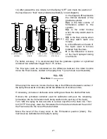
10) Check the position of the liquid level or “initial” mark (indicated as Mark (i) in
next diagram).
11) With the engine running, move the spray switch at the remote control to the
“ON” position for one minute.
20
6) Loosen the jam nut and rotate the
metering - valve knob to the valve setting
to obtain the desired flow rate according to
the flow table. Tight down the jam nut to
prevent the valve setting from accidentally
be changed
7) Rotate the lever of the 3-way valve to
the flush position (pointing up).
8) With the engine running, move the
spray switch at the remote control to the
“ON” position.
9) Let the machine spray for few seconds
to remove any air bubbles from the tube,
then turn the Spray OFF.
1) Locate the machine in an open and well
ventilated place.
2) Verify that the spray switch at the remote
control is in the “OFF” position.
3) Remove the end of the flush tube from
the tube holder (see diagram).
4) Prepare a graduate cylinder or container
with at least 10 oz (300 ml) of formulation.
5) Insert the end of the Flush Tube into the
container with formulation.
MACHINE CALIBRATION
3-WAY VALVE
TUBE
HOLDER
JAM
NUT
METERING
VALVE
KNOB
FLUSH
TUBE
Summary of Contents for 1 Series
Page 1: ......
Page 7: ...7 ...
Page 8: ...8 8 ...
Page 35: ...35 ...
Page 36: ...36 ...
Page 37: ...37 ...
Page 38: ... 38 ...
Page 39: ...39 ...
Page 40: ...40 ...
Page 41: ...41 ...
Page 42: ...42 ...
Page 43: ... 43 ...
Page 44: ... 44 ...
Page 45: ... 45 ...
Page 46: ...4 ...
Page 47: ...47 ...
Page 48: ...48 ...
Page 49: ...49 ...
Page 50: ...50 ...
Page 52: ...cccjlqvqwqxzc x vlj z l lqvqwq j z jklmnooo pw t p yvxmkrq vvrxmyz wzvwmj rrvqmm mmks wvm 52 ...
Page 55: ...cccjlqvqwqxzc x vlj z l lqvqwq j z jklmnooo k vrmyqyzv xm swmksrzvwmm mmks wvmn 55 ...

