background image

TROUBLESHOOTING GUIDE

SYMPTOM

POSSIBLE CAUSE

CORRECTIVE ACTION

1. RECOIL STARTER FAILS TO

A. DEFECTIVE RECOIL STARTER

A.  CHECK RECOIL STARTER.

CRANK THE ENGINE

SERVICE IT IF REQUIRED.

B. BELT TRANSMISSION WITH

B. CHECK BELT AND PULLEYS

OBSTRUCTIONS

FOR OBSTRUCTIONS.

C. ENGINE LOCKED UP

C. CHECK THE ENGINE FOR ROTATION.

CONSULT THE NEAREST SERVICE CENTER

D. BLOWER LOCKED UP

D. INSPECT BLOWER FOR ROTATION

CONSULT THE NEAREST SERVICE CENTER

2. ENGINE HARD TO START

A. ENGINE KILL SWITCH IN

A. PLACE SWITCH IN "ON"  OR "RUN"

OR STOPS

STOP POSITION.

POSITION.

B. FAULTY START-STOP SWITCH

B. REPLACE FAULTY SWITCH.

(ENGINE KILL SWITCH).

C. NO FUEL OR CONTAMINATED FUEL.

C. ADD FUEL OR CLEAN TANK AND REFUEL.

D. CLOGGED FUEL FILTER

D. CLEAN FILTER (IF POSSIBLE) OR REPLACE IT.

E. SPARK PLUG FAULTY

E. CLEAN OR REPLACE SPARK PLUG

F. TERMINAL LOOSE OR WIRING

F. TIGHTEN LOOSE TERMINALS, REPLACE

DEFECTIVE

DEFECTIVE WIRING.

G. SPARK PLUG WIRE DISCONNECTED

G. CONNECT SPARK PLUG WIRE.

H. LOOSEN GASOLINE HOSE OR

H. TIGHTEN LOOSE CLAMPS OR CHANGE

PERFORATED GASOLINE HOSE.

THE GASOLINE HOSE.

3. ENGINE MISSES OR 

A. START-STOP SWITCH (KILL SWITCH)

A. PLACE SWITCH IN "ON"  OR "RUN"

RUN ERRATICALLY.

CONTROL IN STOP POSITION.

POSITION.

B. FAULTY START-STOP SWITCH

B. REPLACE FAULTY SWITCH.

(ENGINE KILL SWITCH).

C. NO FUEL OR CONTAMINATED FUEL.

C. ADD FUEL OR CLEAN TANK AND REFUEL.

D. CLOGGED FUEL FILTER

D. CLEAN FILTER (IF POSSIBLE) OR REPLACE IT.

E. CARBURETOR MOUNTED GASKED

E. TIGHTEN BOLTS, REPLACE GASKET

LEAKS

IF REQUIRED.

H. VACUUM CREATED INSIDE FUEL TANK

H. LOOSE THE  FUEL TANK CAP, IF IMPROVES,

CHECK OR REPLACE TANK VENT.

4. ENGINE KNOCKS OR

A. SPARK ARRESTOR CLOGGED.

A. CLEAN OR REPLACE.

DEVELOPS NOISE.

B. FLYWHEEL LOOSE.

B. CONSULT NEAREST SERVICE CENTER.

C. SHAFT ADAPTOR/PULLEY LOOSE.

C. CONSULT NEAREST SERVICE CENTER.

D. LOOSE BELT.

D. TIGHTEN LOOSE BELT.


 33 


Summary of Contents for 1 Series

Page 1: ......

Page 2: ...Mini Lite ULV Mister TM Copyright 2004 Curtis Dyna Fog Ltd Mini Lite is a trademark of Curtis Dyna Fog Ltd Dyna Fog is a Registered Trademark of Curtis Dyna Fog Ltd U S and Foreign Patents Pending 2 ...

Page 3: ...ions 17 Stopping Instructions 18 Operator Safety 18 Remote Control Box 19 Machine Calibration 20 Flushing System 22 Emergency By Pass of the Solenoid Valve 23 Engine Maintenance 24 Speed Adjustment 24 Air Filter 24 Fuel Filter 25 Spark Plug 25 Muffler 25 Engine Fins 25 Poly V Belt and Sheave Drive 26 Belt Alignment 26 Belt Tension 27 Blower Assembly 28 Inspection of the Blower 28 Air Filter Assemb...

Page 4: ...s it is desirable to treat a given area with the least amount of insecticide that can be made to be effective The most efficient method is to break up the liquids into aerosols and distribute these fine droplets over the target area The small droplets stay suspended for longer periods of time due to their size and are distributed more evenly remaining effective longer The term ULV is an abbreviati...

Page 5: ...tenance free rechargeable battery with protective case NOZZLE Single high output MicrotecTM nozzle mounted on adjustable boom Optional Remote nozzle kit with higher output BOOM Adjustable 360 in the vertical plane and 360 in the horizontal plane Adjustable height TANKS Corrosion resistant high density Polyethylene Formulation 1 25 U S Gallons 4 72 liters Gasoline 33 3 oz 1 Lt FRAME High Strength W...

Page 6: ... causes liquid to be drawn from the formulation tank thru a 3 way selector valve onto a metering valve into a 2 way solenoid valve and to the nozzle The nozzle has six stationary fins that create a swirling effect of the air mass as it leaves each nozzle In the center of this swirling air mass is a liquid supply spray tube The spray tube directs the formulation into the air mass where it is sheare...

Page 7: ...7 ...

Page 8: ...8 8 ...

Page 9: ...h water at once if contaminated with electrolyte acid Do not charge in gas tight container Do not short the battery terminals Do not incinerate Unlawful to discard in landfill Recycle with automotive battery scrap at an EPA or other registered facility Automatic Sealed Lead Acid Battery Charger This charger is designed to fully charge a battery and maintain it at the proper storage voltage without...

Page 10: ...ed openings to prevent moisture and or exhaust gases from entering the cab 3 Using the 2 hold down brackets used for mounting the machine to the shipping skid securely mount the machine to the bed of the vehicle see diagram below Depending on the type of bed surface it may be necessary to use additional mounting hardware to secure the machine Dyna Fog offers an ATV Wheel mounting kit to fit a wide...

Page 11: ...ich is colorless and odorless and can be fatal CAUTION DO NOT OPERATE ENGINE WITHOUT MUFFLER NOTE The engine is equipped with a muffler that has spark arrestor which is required in some States DO NOT TOUCH HOT MUFFLER CYLINDER OR FINS WHEN HOT AS CONTACT MAY CAUSE BURNS EXCEPT FOR ADJUSTMENT DO NOT OPERATE THE ENGINE IF AIR CLEANER OR COVER DIRECTLY OVER THE CARBURETOR AIR INTAKE IS REMOVED DO NOT...

Page 12: ...ct of some formulations the severity of which depends upon the chemical used mist density and the length of time of direct exposure IT IS THE OPERATOR S RESPONSIBILITY TO DISCOURAGE ANYONE FROM PLAYING IN THE MIST OR BEING NEAR THE MOVING VEHICLE 6 FORMULATIONS Ensure that formulations are applied only in strict compliance with the formulation label as well as local state and federal regulations a...

Page 13: ...SE FORMULATION READ AND THOROUGHLY UNDERSTAND ALL INFORMATION CAUTIONS AND WARNINGS ON THE FORMULATION LABEL WHICH MAY AFFECT PERSONAL SAFETY KNOW ANY DANGERS OF THE SOLUTION USED AND KNOW WHAT TO DO IN CASE OF AN ACCIDENT INVOLVING THE SOLUTION ALWAYS USE THE APPROPRIATE SAFETY EQUIPMENT AND DRESS ACCORDING TO THE CHEMICAL FORMULATION WHICH IS BEING USED WARNING DO NOT USE ANY SUBSTANCES FROM UNM...

Page 14: ...nd mounted securely and the strap is proper and tight 9 Verify that all safety equipment is in place and is in proper working order 10 Verify that the flow rate control has been calibrated and is dispensing formulation in accordance with the manufacturers label requirements CAUTION BEFORE PROCEEDING WITH ANY SPRAYING OPERATION THE OPERATOR SHOULD BE THOROUGHLY FAMILIAR WITH STARTING AND STOPPING T...

Page 15: ...f a centipoise CP Generally the thicker the liquid the greater the viscosity and the higher the CP number Examples of some liquid viscosities are LIQUID VISCOSITY CP WATER 1 DIBROM 3 4 DOW MFC 3 4 PYRETHRIN RESMETHRIN 6 7 DURSBAN 1 5 ULV 12 14 TECHNICAL MALATHION 28 TO MEASURE THE FLOWABILITY VISCOSITY OF YOUR FORMULATION 1 Place a sample of the formulation liquid to be dispensed in the relative f...

Page 16: ...e will produce 90 of the droplets below 20 microns ULV when used at the recommended flow rates This meets the requirements of all current chemical labels for controlling flying insects When the high flow rate is discharged through a single nozzle the Mini LiteTM will produce larger droplets suitable for applying a residual deposit to vegetation and any other surface Note Always handle and dispose ...

Page 17: ...1 Set ignition switch engine kill switch to ON Run position See below right diagram 2 Depress priming bulb several times to purge air in carburetor until the fuel flows through return pipe See below left diagram 3 Pull choke lever upward to choke position closed See below middle diagram 4 Pull recoil starter briskly taking care to keep the handle in your grasp and not allowing it to snap back PRIM...

Page 18: ...gy to the solenoid valve 2 Move the engine kill switch to the stop down position OPERATOR SAFETY Keep all loose items ie Clothing hair jewelry etc away from all moving parts Many of the formulations which can be dispensed with this machine are highly toxic and require special safety equipment Read and observe the formulation label safety precautions warnings and procedures before operating machine...

Page 19: ...OX ASSEMBLY IMPORTANT Be sure to turn OFF after operation of machine to prevent discharging battery Some users prefer to disconnect the remote control from the machine to avoid the discharge of the battery if the switch is left in ON when the engine is not working Keep the remote control unit where it will not be damaged or lost while the machine is not working 19 FUSE HOLDER SWITCH TO SOLENOID VA...

Page 20: ...nut to prevent the valve setting from accidentally be changed 7 Rotate the lever of the 3 way valve to the flush position pointing up 8 With the engine running move the spray switch at the remote control to the ON position 9 Let the machine spray for few seconds to remove any air bubbles from the tube then turn the Spray OFF 1 Locate the machine in an open and well ventilated place 2 Verify that t...

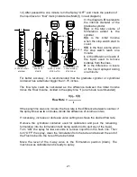
Page 21: ...LE SELECT A MARK i START STOP WATCH AFTER ONE MINUTE CHECK MARK f STOP SPRAY MARK i MARK f i V f V o V For better accuracy it is recommended that the graduate cylinder or cylindrical container has a diameter bigger than 1 75 inches The flow rate could be calculated as the difference between the Initial Volume minus the Final Volume divided in the spray time t one minute recommended V i V f Flow Ra...

Page 22: ...izontal turn the engine kill switch to the Stop OFF position The manual 3 way valve is used as a selector to route either Formulation or Flushing solution from their respective tank container to the nozzle To flush the system locate the machine in an open and well ventilated place and perform the following procedure 1 Verify that the spray switch at the remote control is in the OFF position 2 Remo...

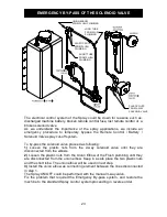
Page 23: ... plastic nuts from the Union Elbow of the Flush plumbing until they are disconnected from the union elbow Keep in a safe place the two plastic nuts and the short tube The union elbow will be used in next step 3 Install the union elbow as connecting element between the lines disconnected in step 1 The Spray ON OFF could be performed with the manual 3 way valve Fix the problem that required the Emer...

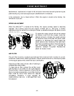
Page 24: ...plastic plate counter clockwise then tight down the screw to hold the position Check the speed with a tachometer after 5 or 7 minutes of operation readjust if required Reinstall the plastic air cleaner cover AIR FILTER The air filter must be cleaned periodically from dust and dirt in order to avoid Carburetor malfunctions Starting problems Engine power reductions Unnecessary wear on the engine par...

Page 25: ...heck the electrode gap Readjust if required The correct gap is 024 6 mm The spark plug should be replaced after about 100 hours of operation or early if the electrodes are badly eroded Note in some areas local laws requires using a resistor spark plug to suppress ignition signals If this machine was originally equipped with resistor spark plug use the same type of spark plug for replacement MUFFLE...

Page 26: ...from the machine for maintenance purposes use a metal strip or similar of 90 23 mm wide as spacer to reinstall the engine in the appropriated place Be sure the surface of the big pulley of the engine makes flat contact with the spacer and the other edge of the spacer makes full contact with the vertical wall of the channel assembly The 90 distance should remain after tighten down the bolts to the ...

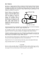
Page 27: ...irable effects as shorter life of bearings engine and blower power reduction higher temperature etc Do not install a new belt on worn sheaves Such sheaves should be replaced to insure a proper fit of the belt in the grooves and prevent slippage and premature belt wear If sheave s change is required they are sold already assembled with the shaft for the blower or on the shaft adapter for the engine...

Page 28: ...Stainless steel air filter guard assembly Working pressure 2 to 3 psi depending of number of nozzles and engine speed Tangential bypass discharge to separate working air from bearing housing BLOWER ASSEMBLY SHOWING CROSS SECTION INSPECTION OF THE BLOWER The Blower should be checked periodically testing the bearings for abnormal conditions or excessive wear checking the rotating fans and other comp...

Page 29: ...filter the critical point is around the nut washer on the aluminum of the fan If high corrosion is present a detailed inspection should be performed too PRELIMINARY INSPECTION OF THE BLOWER After inspected if the Blower Assembly looks in good condition reassembly the belt tighten the blower bolts and tensioning the belt as indicated at the Belt Transmission section reinstall the Guard Assembly and...

Page 30: ...re tight CAUTION Do not run the machine without the Inlet Filter assembly as this would cause serious damage to the blower unit or personal injury REMOVAL AND CLEANING If cleaning procedure is required for the inlet filter loose and remove the three nylock nuts washers bolts that hold the filter assembly to the thermoset fan end bracket Clean the stainless screen in an approved solvent dry with co...

Page 31: ...PLACE SPARK PLUG ROTARY BLOWER CHECK AIR FILTER PRELIMINAR INSPECTION BELT TRANSMISSION CHECK BELT AND PULLEYS CHECK TENSION CHANGE BELT OTHERS FLUSH LIQUID SYSTEM CHARGE BATTERY CHECK FRAME GUARDS CLEAN MACHINE NOTE THE INTERVALES SHOWN REPRESENT AN APPROXIMATE TIME PERIOD FOR PERFORMING THE MAINTENANCE SHOWN DEPENDING ON THE ACTUAL OPERATING ENVIRONMENTAL CONDITIONS IT MAY BE NECESSARY TO PERFOR...

Page 32: ... the S2 button for 4 seconds The right most digit on the LCD will flash and the service icon will be displayed Pressing and holding the S1 button will cause the flashing digit to automatically increment When the desired number has been reached release the S1 button and press the S2 button for 1 second to increment to the next digit Repeat above steps until the service time interval has been entere...

Page 33: ...PLUG F TERMINAL LOOSE OR WIRING F TIGHTEN LOOSE TERMINALS REPLACE DEFECTIVE DEFECTIVE WIRING G SPARK PLUG WIRE DISCONNECTED G CONNECT SPARK PLUG WIRE H LOOSEN GASOLINE HOSE OR H TIGHTEN LOOSE CLAMPS OR CHANGE PERFORATED GASOLINE HOSE THE GASOLINE HOSE 3 ENGINE MISSES OR A START STOP SWITCH KILL SWITCH A PLACE SWITCH IN ON OR RUN RUN ERRATICALLY CONTROL IN STOP POSITION POSITION B FAULTY START STOP...

Page 34: ...MISALIGMENT BELT SHEAVES 8 BLOWER WILL NOT OPERATE A DEFECTIVE BELT A CHECK ALIGMENT AND TENSION WHILE ENGINE IS RUNNING REPLACE IF REQUIRED B BEARINGS WEARING OUT B CONSULT NEAREST SERVICE CENTER C NUT LOOSE AT THE BLOWER SHAFT C CONSULT NEAREST SERVICE CENTER 9 BLOWER EXTREMELY NOISY A LOOSE INTAKE AIR FILTER A TIGHTEN LOOSE SCREWS NUTS C NUT LOOSE AT THE BLOWER SHAFT C CONSULT NEAREST SERVICE C...

Page 35: ...35 ...

Page 36: ...36 ...

Page 37: ...37 ...

Page 38: ... 38 ...

Page 39: ...39 ...

Page 40: ...40 ...

Page 41: ...41 ...

Page 42: ...42 ...

Page 43: ... 43 ...

Page 44: ... 44 ...

Page 45: ... 45 ...

Page 46: ...4 ...

Page 47: ...47 ...

Page 48: ...48 ...

Page 49: ...49 ...

Page 50: ...50 ...

Page 51: ...cccjlqvqwqxzc x vlj z l lqvqwq j z jklmnooo pqrstuvwxmjsyz txms tszs tmm mmks wvm szv j wzmt vw uvypwsjzs t zq p vtzy ª ª ª ª ª ª ª ª z ª qv q l ª 51 ...

Page 52: ...cccjlqvqwqxzc x vlj z l lqvqwq j z jklmnooo pw t p yvxmkrq vvrxmyz wzvwmj rrvqmm mmks wvm 52 ...

Page 53: ... l lqvqwq j z jklmnooo pw t p yvxmkrq vvrxmyz wzvwmj rrvqmm mmks wvm szv j wzmt vw uvypwsjzs t zq p vtzy ª ª ª ª z qv q l qvw q q v q v q µ qv q w l j µ ª j j q q v lz z lq v ª j j z l q qv ª j j ª ª j ª jª ª ª ª ª ª ª ª 53 ...

Page 54: ...z jklmnooo kkrvwxm kkrvwmp vwmm mmks wvm szv j wzmt vw uvypwsjzs t zq p vtzy ª ª ª ª ª z ª ª ª ª ª ª z ª qv q l ª ª ª ª ª ª ª ª ª ª ªª ª ª ª z ª ª ª qv q l ª ª ª qv q l ª qv q l ª ª ª ª ª ª ª ª ª ª ª ª ª w zv l x x z z v z ql zv ºº 54 ...

Page 55: ...cccjlqvqwqxzc x vlj z l lqvqwq j z jklmnooo k vrmyqyzv xm swmksrzvwmm mmks wvmn 55 ...

Page 56: ...l lqvqwq j z jklmnooo k vrmyqyzv xm swmksrzvwmm mmks wvmn szv j wzmt vw uvypwsjzs t zq p vtzy ª ª ª ª ª ªª ª ª ª ª ª ª ª ª ª ª ª ª ª ª ª ª ª ª ª ª qv q l ª ª ª ª ª jª ª ª ª ª ª ª ª ª z ª qv q l ª ª ª j ª ª ª qv q l qv q l 56 ...

Page 57: ...cccjlqvqwqxzc x vlj z l lqvqwq j z jklmnooo wvp srmyz wzvwmm mmks wvm szv j wzmt vw uvypwsjzs t zq p vtzy ª ª ª ª 57 ...

Page 58: ...cccjlqvqwqxzc x vlj z l lqvqwq j z jklmnooo p w wvz wmm mmks wvm szv j wzmt vw uvypwsjzs t zq p vtzy v q lz q w l ª zvlq v v q xq l ª zl q q q v q µ ª ª ª ª ª 58 ...

Page 59: ...1 3 gallon tanks available in 115 and 230 VAC COMBUSTION ENGINE DRIVEN ULV AEROSOL GENERATORS Truck mounted Units powered by 8 9 11 18 and 20 HP four cycle OHV Gasoline Engines Diesel versions also available One two four and eight nozzle configurations Patented full remote control of boom functions rotation of turntable and angle of nozzles available on certain models Your choice of Gear Piston or ...

Reviews: