


PAGE 15
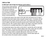
BENCH TEST INSTRUCTIONS
Parts Needed:
Standard 1156 automotive bulb in a socket, Charged 12V battery, Alligator clip test
leads OR wire and wire nuts, 51515 / 51516 Quick plug with pigtails OR push pins
NOTE:
If a quick plug pigtail is not available push pins can be used to make
a direct connection to the female terminals of the TriFlex quick plug housing.
CAUTION:
Ensure that the brake control wires, quick plug wires, push pins
and test leads do not make contact with each other or any other metal surface –
failure to do so may damage the brake controller.
Brake Controller Setup
Connect the quick plug to the TriFlex to provide accessible wires for bench testing.
Connect the white ground wire of the TriFlex and the ground wire
of the bulb to the negative terminal of the 12V battery.
Leave the red brake input wire and blue output wire unconnected.
Connect the black battery wire of the TriFlex to the positive terminal of the 12V battery.
If the brake controller is wired properly and the TriFlex is operational the display will
flash the current sensitivity level (ex. ) followed by a single decimal point .
Ensure the TriFlex is level to the bench surface and connect the
signal wire of the bulb to the blue brake output wire of the TriFlex.
Summary of Contents for Triflex Brake Controller
Page 20: ...PAGE 20 NOTES...