background image

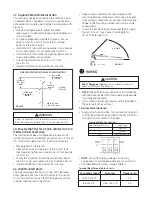
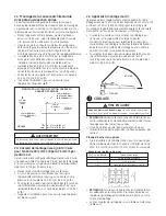
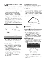
FIGURE 7

Set Screws

45° MAX

2c.  Square Pole Architectural Arm

This luminaire has been configured the same as 4 and 
no adapter plate is needed to mount to a square pole.  
Hole pattern on square pole shall be in  accordance with 
Figure 6.
•  Place fixture against pole. Adjust nut plate  
  (See Figure 3.) to desired hole spacing and tighten set  
  screw on plate.
•  For legacy diagonal bolt pattern (Figure 5.) set nut  
  plate to 4.58” (116 mm). For all other mounting 
  patterns reference Figure 2.
•  Install 3/8 bolt, lock washer and washer in top hole as  
  shown and tighten into nut plate. (See Figure 4).
•  Install 3/8 bolt, lock washer and washer below arm as  
  shown and tighten into nut plate.
•  Torque top and bottom bolts to 25-32 ft-lbs  
  (34-43 N-m).
•  Inspect installation to ensure fixture is secure.

• 

NOTE: Make all electrical connections in accordance  

  with the National  Electrical Code and any applicable   
  local code requirements.  
•  Strain relief for incoming power must be  provided in  
  the pole top by the customer.
Terminal Block (Optional)
•  Supply Wire Type and Size, for Customer Connection  
  to (if option present) Terminal Block: 16 AWG (1.5mm

2

)  

  to 6 AWG (10mm

2

) Solid or Stranded.

WIRING

3

CAUTION

Risk of Damage or Injury:  Door should be closed with 
screw until fixture in final location.

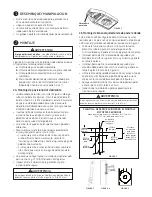
DRILLING TEMPLATE SQUARE POLE MOUNTING

FIGURE 6

2.1960 in.

(56 mm)

.438 in. DIA.

(11 mm DIA.)

(2 PLACES)

5.2500 in.

(133 mm)

(MIN.)

1.250 in. DIA.

(32 mm DIA.)

(HOLE)

.656 in. (17 mm)

1.312 in. (33 mm)

4.3920 in.

(112 mm)

2d. Knuckle Slipfitter for 2-3/8 in. (60mm) to 3.0 in. 

(76mm) OD Vertical Tenon

This luminaire has been configured to provide 0 to 45° 
vertical aiming in 5° increments and mount on 2-3/8-inch 
O.D. (73mm) through 3-inch O.D. (76mm) vertical pipe.

•  Place slipfitter on the tenon.
•  Clamp the fixture to the pipe with three set screws  
  (See Figure 6) Tighten set screws to 18-22 foot pounds  
  (24-30 N-m).
•  To aim the luminaire, loosen the knuckle bolt, adjust  
  the aim 0 to 45°, and tighten to 45-50 ft-lbs (61-68 N-m).
•  Inspect installation to ensure fixture is secure.

•  Open wiring compartment cover loacted on the  
  mounting bracket. Make electrical connections and  
  close wiring compartment cover. Seal wall mounting  
  flange to the mounting surface with silicone, caulk,  
  or equivalent.
•  To aim the luminaire loosen the knuckle bolt, adjust  
  the aim 0° to 45° (see Figure 7), and tighten to  
  45-50 ft-lbs (61-68 N-m).

Terminal Block Connections:

Terminal Board Position 

Supply Type


L1 

High Line

 G 

Ground


N/L2 

Low Line/Neutral

• 

NOTE: Verify that supply voltage is correct by   

  comparing it to nameplate inside door or on carton.
•  See table below for screw torques (Table 1).

WARNING

Under no conditions should architectural arm mounting  

bolts be torqued to greater than 32 foot pounds (43 N-m).

Terminal Block Torque Table UL Units:

Wire Range Copper 

Aluminum 

Torque (in lbs)

  10-16 SOL,STR 


30

  8-6 SOL,STR 

STR6, SOL, STR 

45

2e.  Wall Mounted Units:

The wall mounting plate has four .438 inch clearance 
holes spaced 4.375 (H) x 2.875 (V) inches for mounting.  
Do not mount the unit such that the hinge side of door 
is higher than the latch side of door

Summary of Contents for Evolve

Page 1: ...vice must accept any interference received including interference that may cause undesired operation This Class A Lighting Equipment complies with Canadian standard ICES 005 A NMB 005 A Note This equipment has been tested and found to comply with the limits for a Class A digital device pursuant to part 15 of the FCC Rules These limits are designed to provide reasonable protection against harmful i...

Page 2: ... 45 vertical aiming angle 2a Slipfitter The pipe clamp See Figure 1 accommodates 1 1 4 inch 1 660 OD through 2 inch 2 375 O D pipe Adjust the clamp bolts so the opening is slightly larger than pipe Insert pipe into back of the luminaire until it contacts and sits on the center leveling steps extended from top of housing The luminaire may be leveled by selecting different steps To level hold lumina...

Page 3: ...12 in 33 mm 4 3920 in 112 mm 2d Knuckle Slipfitter for 2 3 8 in 60mm to 3 0 in 76mm OD Vertical Tenon This luminaire has been configured to provide 0 to 45 vertical aiming in 5 increments and mount on 2 3 8 inch O D 73mm through 3 inch O D 76mm vertical pipe Place slipfitter on the tenon Clamp the fixture to the pipe with three set screws See Figure 6 Tighten set screws to 18 22 foot pounds 24 30 ...

Page 4: ...ion on occupancy sensor behavior with GE LightGrid is available Visit www LED com for more informantion These instructions do not purport to cover all details or variations in equipment nor to provide for every possible contingency to be met in connection with installation operation or maintenance Should further information be desired or should particular problems arise which are not covered suffi...

Page 5: ...imites ont été établies pour assurer une protection raisonnable contre les interférences nuisibles lorsque l équipement est utilisé dans un environnement commercial Cet équipement produit utilise et peut émettre de l énergie radio électrique et s il n est pas installé et utilisé conformément aux instructions peut provoquer des interférences nuisibles aux communications radio L utilisation de cet é...

Page 6: ...ent plus grande que le diamètre du tuyau qui est utilisé Introduisez le tuyau de montage dans la partie arrière du luminaire jusqu à ce qu il fasse contact avec les gradins de mise au niveau centraux qui font saillie à partir du dessus de bâti et jusqu à ce qu il porte sur ces derniers Le luminaire peut être mis au niveau en choisissant l un ou l autre des différents gradins Pour mettre au niveau ...

Page 7: ...DE SECTION CARRÉE AU GABARIT DE PERÇAGE FIGURE 6 56 mm 2 196 po 11 mm DE DIAM 0 438 po DE DIAM DEUX ENDROITS 133 mm 5 25 po MIN 32 mm DE DIAM 1 25 po DE DIAM TROU 17 mm 0 656 po 33 mm 1 312 po 112 mm 4 392 po 2d Raccord de montage lisse à joint articulé pour tenon de 60 mm 2 3 8 po à 76 mm 3 po de diam ext Ce luminaire a été configuré spécifiquement pour procurer une visée verticale d un angle de ...

Page 8: ...r Le capteur comporte un ensemble distinct de directives de programmation qui est inclus Une documentation complémentaire sur le comportement du capteur de présence avec trame lumineuse est disponible Veuillez visiter LED com pour obtenir de plus amples renseignements à ce sujet Ces instructions ne prétendent pas couvrir tous les détails ou variations de l équipement ni envisager toutes les éventu...

Page 9: ...da Este equipo de iluminación de clase A cumple con la norma canadiense ICES 005 A NMB 005 A Nota Este equipo ha sido probado y cumple con los límites para la Clase A de aparatos digitales conforme a la parte 15 de las Reglas FCC Estos límites están diseñados para proveer protección necesaria para contrarrestar interferencia perjudicial cuando el equipo está en operación en un ambiente comercial E...

Page 10: ...juste los dos pernos de la abrazadera para tubo para que la abertura de la abrazadera sea un poco más grande que el tamaño del tubo que se va a utilizar Inserte el tubo de montaje en la parte posterior de la luminaria hasta que haga contacto y siente en los peldaños de nivelación del centro que se extienden desde la parte superior del gabinete La luminaria se puede nivelar seleccionando peldaños d...

Page 11: ...minaria esté colocada en su posición final PLANTILLA DE PERFORACIÓN PARA EL MONTAJE EN POSTES CUADRADOS FIGURA 6 2 1960 in 56 mm 438 in DIA 11 mm DIA 2 PUNTOS 5 2500 in 133 mm MIN 1 250 in DIA 32 mm DIA ORIFICIO 656 in 17 mm 1 312 in 33 mm 4 3920 in 112 mm 2d Posicionador deslizante de junta articulada para espiga de 2 3 8 in 60 mm a 3 0 in 76 mm de diámetro exterior Esta luminaria se ha configura...

Page 12: ...ón el cual está incluido Está disponible documentación adicional acerca del comportamiento del sensor de ocupación con la rejilla de luz Visite LED com para obtener más información Estas instrucciones no pretenden cubrir todos los detalles o variaciones de equipo ni cada posible contingencia encontrada en conexión a la instalación operación o mantenimiento Si más información es requerida o ciertos...

Reviews: