background image

2. Smart-Flex (FLX-4629) Operation Instructions

12

PNEG-1186

 Smart-Flex (FLX-4629) Operation Instructions

Alarms

There are five (5) alarms modes for the Smart-Flex:

To reset alarms 2 through 5 above, you must push the 

Set/Clr

 button.

* When the pressure switch is activated, it will not sound an alarm when in extension mode.

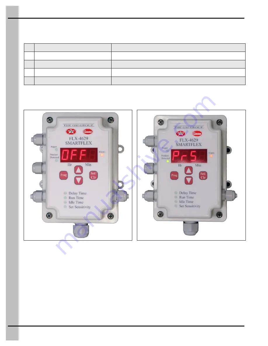
Figure 2G 

Figure 2H 

1

Toggle switch turned off

Display will flash “OFF” 

(See Figure 2G.)

* 2

Pressure switch activated

Display will flash “PrS” and sound an alarm 

(See Figure 2H.)

3

Maximum Run Time exceeded

Display will flash “run” and sound an alarm 

(See Figure 2I on Page 13.)

4

Maximum Idle Time exceeded

Display will flash “IdL” and sound an alarm 

(See Figure 2J on Page 13.)

5

Lost communication with Network Master

Display will flash “AC14” 

(See Figure 2K on Page 13.)

Summary of Contents for Smart-Flex FLX-4629

Page 1: ...PNEG 1186 Smart Flex FLX 4629 Operation Instructions Owner s Manual PNEG 1186 Date 01 01 15 ...

Page 2: ... Operation Instructions All information illustrations photos and specifications in this manual are based on the latest information available at the time of publication The right is reserved to make changes at any time without notice ...

Page 3: ...e Unit I D Number Only Used with Network Master 10 Sensor Setting Guidelines 11 Alarms 12 Chapter 3 Wiring Diagrams 14 Standard Configuration 14 Relay Box 15 Standard Mode 16 Extension Mode 17 Chain Disk Mode 18 IR Plus Feed Sensor or N O Micro Switch 19 Chapter 4 Smart Flex Optional Equipment 20 Smart Flex Extension Unit FLX 4820 20 Lid Clear Protector Cover Kit FLX 4738 21 Chapter 5 Parts List 2...

Page 4: ... this manual and its safety instructions is a misuse of the equipment and may lead to serious injury or death DANGER WARNING CAUTION CAUTION This is the safety alert symbol It is used to alert you to potential personal injury hazards Obey all safety messages that follow this symbol to avoid possible injury or death This symbol indicates a potentially hazardous situation which if not avoided may re...

Page 5: ...fire department near your telephone Keep Emergency Equipment Quickly Accessible Wear Protective Clothing Wear close fitting clothing and safety equipment appropriate to the job Remove all jewelry Tie long hair up and back Wear safety glasses at all times to protect eyes from debris Wear gloves to protect your hands from sharp edges on plastic or steel parts Wear steel toed boots to help protect yo...

Page 6: ...o go empty The Delay Time can be decreased as the animals in a barn get older and eat more or it can be permanently kept at the minimum time that will work for all situations including when the animals are older To Set the Delay Time 1 Push the PROG button until the green LED next to the Delay Time begins to flash The display will also flash with the 4 digit current setting 2 Push the arrow button...

Page 7: ...to flash The display will also flash with the 4 digit current setting 2 Push the arrow button up or down to increase or decrease the Run Time The Run Time can be adjusted in one minute increments within a range between zero and 99 hours and 59 minutes By pushing the arrow button once the time will increment by one minute Holding the arrow button down it will increment at a faster rate 3 Once the R...

Page 8: ...ED next to the Idle Time begins to flash The display will also flash with the 4 digit current setting 2 Push the arrow button up or down to increase or decrease the Idle Time The Idle Time can be adjusted in one minute increments within a range between zero and 99 hours and 59 minutes By pushing the arrow button once the time will increment by one minute Holding the arrow button down it will incre...

Page 9: ...stem senses falling feed and shuts off prematurely reduce the setting by one level and try it again If at a given sensitivity level the system does not sense the feed and does not shut off when full increase the setting by one level and try it again See Figure 2D IMPORTANT When attempting to set sensor at levels 1 through 6 prior to adjustment the sensor must be placed in the grommet with no feed ...

Page 10: ...ocation for each Smart Flex for use when programming the Network Master To Set the Unit I D Number 1 Push both arrow up and arrow down buttons at the same time then release Initially the default setting of 0000 indicating no unit I D number will be displayed 2 Use the arrow button up or down to scroll through to the desired unit I D number from 0051 through 0075 3 Once the unit I D number is selec...

Page 11: ...iring diagram on Page 18 See Figure 2E Level Ir refers to Infra Red IR Plus Feed Sensor Use this level when connecting to a IR Plus Feed Sensor with no display or when connecting to a hopper level control switch that includes a Normally Open N O Micro Switch See wiring diagram on Page 19 See Figure 2F Sensor Level Settings Figure 2E Chain Disk Situation Level Figure 2F IR Plus Feed Sensor Situatio...

Page 12: ... an alarm when in extension mode Figure 2G Figure 2H 1 Toggle switch turned off Display will flash OFF See Figure 2G 2 Pressure switch activated Display will flash PrS and sound an alarm See Figure 2H 3 Maximum Run Time exceeded Display will flash run and sound an alarm See Figure 2I on Page 13 4 Maximum Idle Time exceeded Display will flash IdL and sound an alarm See Figure 2J on Page 13 5 Lost c...

Page 13: ...2 Smart Flex FLX 4629 Operation Instructions PNEG 1186 Smart Flex FLX 4629 Operation Instructions 13 Figure 2I Figure 2J Figure 2K ...

Page 14: ...14 PNEG 1186 Smart Flex FLX 4629 Operation Instructions 3 Wiring Diagrams Standard Configuration Figure 3A Standard Configuration ...

Page 15: ...3 Wiring Diagrams PNEG 1186 Smart Flex FLX 4629 Operation Instructions 15 Relay Box Figure 3B Wiring Diagram for Relay Box ...

Page 16: ...Flex uses the proximity sensor AP 2984 The two 2 wires from the proximity sensor connect to the terminals in the lid marked Sensor V and Sensor V See Figure 3C This configuration with the proximity sensor AP 2984 is the only one that the set sensitivity levels 1 through 6 correspond to Figure 3C Wiring Diagram for Standard Mode ...

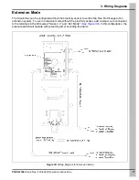
Page 17: ... to control the Flex Flo fill auger of an extension system To use in extension mode without the proximity sensor add a jumper wire connected to the terminals in the lid marked Sensor V and Ext Mode See Figure 3D In this configuration the pressure switch will operate without setting off or sounding the alarm Figure 3D Wiring Diagram for Extension Mode ...

Page 18: ...he proximity sensor is not used In place of the proximity sensor connect a two 2 conductor cord from the terminals in the Smart Flex lid marked Sensor V and Sensor V to the terminals of the chain disk control marked Auger Motor See Figure 3E The set sensitivity must be set to level Cd In this configuration the chain disk feed system will control the Flex Flo auger Figure 3E Wiring Diagram for Chai...

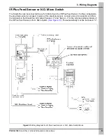
Page 19: ...r this configuration the proximity sensor is not used In place of the proximity sensor connect a two 2 conductor cord from the terminals in the Smart Flex lid marked Sensor V and Sensor V to the corresponding terminals of the IR Plus Feed Sensor or N O Micro Switch See Figure 3F The set sensitivity must be set to level Ir Figure 3F Wiring Diagram for IR Plus Feed Sensor or N O Micro Switch Mode ...

Page 20: ...distance the extension unit can be mounted away from the main Smart Flex control is 200 In addition to the extension unit an Alpha 6344 eight 8 conductor extension wire is needed to connect the two 2 components together The extension wire is available in either 50 length FLX 4821 50 or 200 length FLX 4821 200 Install the Smart Flex extension unit according to the instructions that are supplied wit...

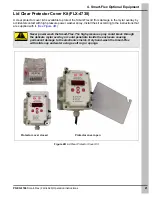
Page 21: ... power washer spray Install the kit according to the instructions that are supplied with it See Figure 4B Figure 4B Lid Clear Protector Cover Kit CAUTION Never power wash the Smart Flex The high pressure spray could break through the delicate mylar overlay or could penetrate inside the enclosure causing permanent damage to the electronics inside Only hand wash the Smart Flex with mild soap and wat...

Page 22: ...22 PNEG 1186 Smart Flex FLX 4629 Operation Instructions 5 Parts List Smart Flex Parts 1 4 6 7 8 5 2 9 3 ...

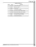
Page 23: ...5183 Box Fuse 1A at 250V 3 FLX 4802 Connector Cord 4 FLX 4799 Top with Printed Circuit Board 5 FLX 4799LB Smart Flex I Top without Printed Circuit Board 6 FLX 4799LB2 Smart Flex II Top without Printed Circuit Board 7 FLX 4801 Smart Flex Printed Circuit Board Bottom 8 AP 2984 Feed Sensor for Smart Flex Control Unit 9 AP 1004 Grommet for Proximity Switch ...

Page 24: ...5 Parts List 24 PNEG 1186 Smart Flex FLX 4629 Operation Instructions Smart Flex Relay Box Assembly FLX 4778 ...

Page 25: ...X 4619 Relay 4 Pole ST N O 240V 1 6 S 8823 Screw TCS23 8 32 x 3 8 HWHS ZN Green 1 7 S 7931 Hex Nut 10 24 SS 4 8 FLX 4561 4 x 6 Electrical Box Gasket 1 9 FLX 4560 4 x 6 Electrical Box Lid Cover 1 10 S 995 Screw MS 10 24 x 1 PHP SS 4 11 DC 1804 Decal CSA Mark FLX 4800 1 12 DC 1635 Decal Smart Flex Relay Box FLX 4778 1 13 DC 1515 Decal 208V 230V 3 PH Wire Label 1 14 S 8183 Screw SMSA 6 x 3 8 PHP ZN 4...

Page 26: ...5 Parts List 26 PNEG 1186 Smart Flex FLX 4629 Operation Instructions AP 4 x 6 Electrical Box Clear Cover Kit AP 4738 ...

Page 27: ...Clear Cover Kit AP 4738 Parts List Ref Part Description Qty 1 AP 4700 Cover Clear 4 x 6 PVC BOX 1 4 Lexan 1 2 AP 4709 Spacer Round Through Hole Nylon Black 0 195 I D x 3 8 O D x 1 1 2 2 3 S 10106 Flat Washer 10 11 16 O D SS 2 4 S 8570 Screw MS 10 24 x 2 1 2 PHP SS 2 5 S 7112 Flat Washer 10 SS 2 ...

Page 28: ...28 PNEG 1186 Smart Flex FLX 4629 Operation Instructions NOTES ...

Page 29: ...H PRODUCTS GSI shall not be liable for any direct indirect incidental or consequential damages including without limitation loss of anticipated profits or benefits The sole and exclusive remedy is set forth in the Limited Warranty which shall not exceed the amount paid for the product purchased This warranty is not transferable and applies only to the original end user GSI shall have no obligation...

Page 30: ... and applicable regulations which should be carefully followed in all cases Authorities having jurisdiction should be consulted before installations are made 1004 E Illinois St Assumption IL 62510 0020 Phone 1 217 226 4421 Fax 1 217 226 4420 www gsiag com CN 315800 AP and Cumberland are a part of GSI a worldwide brand of AGCO Corporation ...

Reviews: