Cubix Corporation
2800 Lockheed Way
Carson City, NV 89706-
0713 ● Page 6
Sales 800.829.0550
http://www.cubix.com
xprm8g3-825urp24-20181001
Normal Power On/Off Procedure
1. With Rack Mount 8 connected to the host computer and running, shut down the host
computer normally.
2. With Rack Mount 8 connected to the host
computer and powered down, switch on the
connected host computer; both Xpander
and host will boot.
3. To run the host PC without Xpander
connected, power down the host, remove
power from Xpander and boot the host.
When you are ready to run Xpander again,
power down the host, connect power to
Xpander and boot the host.
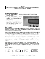
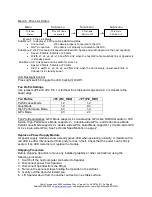
Front Panel LCD
Rackmount 8 front panel LCD provides enclosure details and status. Beneath the LCD are three
buttons: left button scrolls through MIBs, middle button scrolls through the main-menu items and
right button scrolls through sub-menu items.
When you first connect power, Xpander comes up in standby mode. The LCD displays Cubix on
the top line and Corporation on the bottom line. This is the Start menu. Access all other main
menu items by pressing the left button for a MIB, the middle button for a menu selection and
then the right button for a sub-menu selection.
The upper right corner of the LCD shows a flashing asterisk *. This indicates that the on-board
Micro-Controller Unit (MCU) is running properly. If the asterisk is not flashing or the LCD is not
responding, reset the MCU by pressing and holding the left button for 3 seconds while Xpander
is running. A corresponding HB (for heartbeat) LED on the MIB also confirms that the MCU is
working.
When a fault occurs, the LCD will jump to that fault and the LCD backlight will flash on / off.
Press the left button to acknowledge the fault and the LCD will stop flashing and enable normal
operation. The LCD will continue to display the fault at the applicable sub-menu until you clear
the fault.
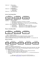
Menu 1: Start Menu
Menu 1
Sub-menu 1
Sub-menu 2
Sub-menu 3
Main menu 1: Cubix Corporation
Warning
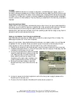
Replace the cover as soon as possible to allow for proper cooling. Do not run Rack Mount 8
without the cover for more than a few minutes.
Cubix
Corporation
c
PCB Assembly
A09180 Rev 1A-0A
c
MCU Firmware
Rel 01 06-20-12
c
Serial Number
10200000
c