background image

54

LUBRICATION GUIDE

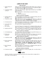
—Before Each Use

NOTE

Lubrication information for optional equipment may be found in the manual which is included with the
specific piece of optional equipment.

1.

Engine filler cap and 
dipstick

Check the oil (with the engine stopped) and add sufficient new oil to bring it to
the

 “FULL”

 mark on the dipstick. Do not overfill. Do not operate the engine if

the oil level is below the

 “LOW”

 mark on the dipstick.

2.

Transmission oil level 
and fill port

Check the oil with the engine stopped. Keep the lubricant up to the 

“FULL”

mark on the dipstick.

NOTE:

 The transmission oil level and fill port services the following:

1.

Rear axle

2.

Hydrostatic transmission

—After Every 10 Hours of Operation

3.

Steering knuckles (2) 
(both sides)

Use 251H EP grease or an equivalent No. 2 multi-purpose lithium grease and
apply sufficient grease to flush out old grease and dirt.

4.

Transmission oil filter 

NOTE:

 After the first 10 hours only, remove the transmission oil filter and

replace with a new filter. Refer to

 “MAINTENANCE.”

  Change the transmission

oil filter after 50 hours and every 100 hours of operation thereafter.

5.

Front axle pivot bolt

Use 251H EP grease or an equivalent No. 2 multi-purpose lithium grease and
apply sufficient grease to flush out old grease and dirt.

6.

Foot and lift control 
pivot points

Use a liberal amount of high grade lubricating oil.

7.

Deck spindles

Use 251H EP grease or an equivalent No. 2 multi-purpose lithium grease and
apply 2 strokes (minimum) or sufficient grease to flush out old grease and dirt.

8.

Spindle belt idler arm

Use 251H EP grease or an equivalent No. 2 multi-purpose lithium grease and
apply  2 strokes (minimum) or sufficient grease to flush out old grease and dirt.

—After Every 30 Hours of Operation

9.

Front wheel bearings

Two or three strokes minimum of the lubricator using 251H EP grease or an
equivalent No. 2 multi-purpose lithium grease.

10. Steering gear 

housing (2)

Every 30 hours or three times a season, use 251H EP grease or an equivalent
No. 2 multi-purpose lithium grease. Apply two strokes with lubricator.

—After Every 50 Hours of Operation

11. Transmission oil filter 

NOTE:

 After the first 50 hours only, remove the transmission oil filter and

replace with a new filter. Refer to

 “MAINTENANCE.”

  Change the transmission

oil filter every 100 hours of operation thereafter.

12. Engine oil drain valve 

and oil filter

While the engine oil is warm, open the drain valve and remove the oil filter, and
drain all of the oil from the crankcase. Close the drain valve. Refer to

“MAINTENANCE,” “FILLING THE CRANKCASE” and “OIL FILTER”

 for

proper oil filling procedure. Refer to 

“LUBRICATION TABLE”

 for the proper

quantity and viscosity to use. 

13. Deck front gauge 

wheels

Use 251H EP grease or an equivalent No. 2 multi-purpose lithium grease and
apply sufficient grease to flush out old grease and dirt

—After Every 100 Hours of Operation

14. Transmission oil filter 

Change the transmission oil filter and replace with a new filter. Refer to

“MAINTENANCE.”

Summary of Contents for 2164

Page 1: ...ark arrester meeting applicable local or state laws if any If a spark arrester is used it should be maintained in effective working order by the operator In the State of California the above is required by law Section 4442 of the California Public Resources Code Other states may have similar laws Federal laws apply on federal lands A spark arrester for the muffler is available through your nearest...

Page 2: ...s The undisputed warranty repairs should be completed in a reasonable amount of time not to exceed 30 days If you have any questions regarding your warranty rights and responsibilities you should contact your authorized dealer The emission warranty is a defects warranty Defects are judged on normal engine performance The warranty is not related to an in use emission test EMISSION CONTROL DEFECTS W...

Page 3: ... sealed battery The positive battery cable has been connected at the factory but the negative cable must be connected Note Make sure the ignition switch is in the OFF po sition before attaching the battery cables 1 Pull the protective cap off the negative terminal of the battery and remove the hex cap screw and nut from the free end of the negative battery cable 2 Connect the negative battery cabl...

Page 4: ...ng Keep this manual in a safe place for future and regular reference and for ordering replacement parts 2 Only allow responsible individuals familiar with the instructions to operate the machine Know the controls and how to stop the machine quickly 3 Do not put hands or feet under the cutting deck or near rotating parts 4 Clear the area of objects such as rocks toys wire etc which could be picked ...

Page 5: ...slopes before operating this unit on a sloped or hilly area If the slope is greater than 15 as shown on the slope gauge do not operate this unit on that area or serious injury could result DO Mow up and down slopes not across Remove obstacles such as rocks limbs etc Watch for holes ruts or bumps Uneven terrain could overturn the machine Tall grass can hide obstacles Use slow speed Choose a low eno...

Page 6: ...s instructed in this manual 8 After striking a foreign object stop the engine remove the wire from the spark plug and thoroughly inspect the mower for any damage Repair the damage before restarting and operating the mower 9 Grass catcher components are subject to wear damage and deterioration which could expose moving parts or allow objects to be thrown For your safety protection frequently check ...

Page 7: ...NSTRUCTIONS DISENGAGE PTO AND SET PARKING BRAKE MOVE THROTTLE CONTROL TO MID POSITION AND TURN KEY OFF STARTING INSTRUCTIONS AVOID SERIOUS INJURY OR DEATH READ OPERATORS MANUAL AND ALL WARNING LABELS BEFORE USING MACHINE GO UP AND DOWN SLOPES NOT ACROSS AVOID SUDDEN TURNS DO NOT OPERATE UNIT WHERE IT COULD SLIP OR TIP IF MACHINE STOPS GOING UPHILL STOP PTO AND BACK DOWN HILL SLOWLY DO NOT MOW WHEN...

Page 8: ...once a year depending on its hours of use CAUTION DO NOT tow your Model 2164 tractor Towing may damage the transmission Place the tractor on a LEVEL SURFACE before pulling the trans mission release lever to the disengaged position The Cub Cadet hydrostatic drive system requires min imal service if the recommended operation and main tenance procedures are followed UNDER NO CIRCUMSTANCES SHOULD YOU ...

Page 9: ... attempting to start or operate the tractor A Low Oil Indicator B Hour Meter C Power Take Off PTO Control Switch D Ignition Light Switch E Throttle Control Lever F Choke Control G Brake Pedal Lock H Cruise Control Lever I Brake Pedal J Forward Control Pedal K Reverse Control Pedal L Lift Handle M Lift Height Indicator N Seat Adjustment Lever O Transmission Release Lever P Fuses Not Shown Q Safety ...

Page 10: ... the control cable will maintain a uniform engine speed NOTE When using power take off operated equip ment best performance is achieved with the throttle lever in the FAST position F CHOKE CONTROL The choke control is operated manually Pull the knob out to ckoke the engine push the knob in to open the choke G BRAKE PEDAL LOCK WARNING The hydrostatic transmission will not hold the tractor on a hill...

Page 11: ...moving the han dle to the desired position then releasing the button It may be necessary to push or pull slightly on the handle to depress the button There is a lift assist spring which reduces the effort needed to lift attachments To adjust spring tension refer to ADJUSTMENTS in Section III M LIFT HEIGHT INDICATOR The lift height indicator is located in the left fender and indicates the height of...

Page 12: ... filler cap is in the center rear of the fender see Figure 7 Figure 7 HOOD AND SIDE PANELS The tractor hood is arranged to swing up and forward for easy access to the engine compartment see Fig ure 8 Whenever engine maintenance is required the side panels can be removed WARNING If the engine has been recently run the engine muffler and surrounding metal surfaces will be hot and can cause burns to ...

Page 13: ...13 Figure 8 UPPER FRONT WING NUT RETAINER WITH TAPERED GUIDE REAR WING NUT GRILLE REAR TAB ON PANEL SIDE PANEL GROOVE IN DASH PANEL GRASP GRASP ...

Page 14: ...e fuel freshness In countries other than the U S A leaded gasoline may be used if it is commercially available and un leaded is not available NOTE Some fuels called oxygenated or reformulated gasolines are gasoline blended with alcohols or ethers Excessive amounts of these blends can damage the fuel system or cause performance problems Do not use gasoline which contains Methanol If any undesirable...

Page 15: ...e s starter motor to cool then try again 7 After the engine starts slowly release the brake pedal As the engine warms up gradually push the choke control knob all the way in Do not use the choke to enrich the fuel mixture except as necessary to start the engine NOTE This engine is designed to give maximum performance and service life if operated with the choke fully open and the throttle in the FA...

Page 16: ... the throttle control in the SLOW position and the choke all the way in turn the ignition key to the START position while slowly pulling the choke out to a position that will allow the engine to start Gradually adjust the choke as needed to keep the engine running until warmed up then push the choke control all the way in DRIVING THE TRACTOR CAUTION Avoid sudden starts excessive speed and sudden s...

Page 17: ...s rocks mounds ruts stumps or other surface irregularities which could cause the tractor to be upset Back the tractor with implement up the steepest portion of each slope you intend to work If the tractor cannot negotiate the slope in reverse the slope is too steep to be worked Avoid turns when driving on a slope If a turn must be made turn down the slope Turning up a slope greatly increases the c...

Page 18: ... power take off switch the tractor s engine will shut off 5 The PTO clutch cannot be operated when the tractor is driving in the reverse direction The PTO switch must in the OFF position when the reverse control pedal is depressed or the PTO clutch will automatically disengage To re engage the PTO clutch release the reverse control pedal move the PTO switch to the OFF position then again pull the ...

Page 19: ...pushed forward or rearward the braking force must be increased 2 Release the brake pedal lock If the tractor cannot be pushed forward or rearward the braking force must be decreased To adjust the braking force refer to Figure 11 and proceed as follows 1 Place the tractor on a level surface with the brake pedal lock disengaged Stop the tractor engine and remove the ignition key 2 While working from...

Page 20: ...tance between the marks and the frame See measurement C in Figure 12 Measurement D should be approximately 1 16 to 1 8 inch less than measurement C on each side of the tractor 5 Manually move each wheel to achieve the required toe in and equal D measurements 6 Loosen the jam nuts from the ball joints See Figure 13 Figure 13 7 Making sure not to move the lower steering arm or either wheel turn the ...

Page 21: ...d to balance the tractor and prevent tipping WARNING The operator presence safety circuit will stop the engine if the seat is empty when the brake pedal is released If an assistant is seated when adjusting the neutral setting use extreme caution to prevent the tractor from tipping or rolling Similar precautions should be taken with any other method of over riding the safety circuit such as placing...

Page 22: ... maintain the adjusted position of the control rods when tightening the screws 4 Raise the rear of the tractor remove the jack stands and lower the tractor ADJUSTING LIFT ASSIST SPRING TENSION The effort required to operate the implement lift handle can be varied by loosening or tightening the lift assist spring adjusting bolt See Figure 16 The bolt can be accessed from the rear of the tractor ins...

Page 23: ... warmed up Adjust the carburetor idle fuel mixture as follows The carburetor on the engine is low emission It is equipped with an idle speed adjustment screw and an idle mixture valve that has an adjustment limiter which allows some adjustment See Figure 17 Figure 17 Start the engine and warm up approximately 5 minutes before adjusting With the engine running place the throttle control in the SLOW...

Page 24: ...wivel should be against the throttle stop See Fig ure 19 If not loosen the casing clamp screw Move the casing and wire in the direction shown by the arrow until the swivel is against the throttle stop Tighten the casing clamp screw and replace the air cleaner Figure 19 The adjustable governor control was set at the factory If adjustment is required consult your Authorized Cub Cadet Service Dealer ...

Page 25: ... oil level between the FULL and the LOW marks on the dipstick When checking the oil level the engine must be cold the dipstick must be withdrawn and wiped clean then screwed all the way into the tube before being withdrawn for a true reading CHECKING THE OIL LEVEL Before each use the oil level of the engine crankcase should be checked to see that it is filled to the correct level Close monitoring ...

Page 26: ...d through your Cub Cadet dealer under part number BS 492932 Refer to the MAINTENANCE CHART and the LUBRICATION TABLE for information regarding the frequency of required oil changes and the quantity and type of oil needed The oil filter is located behind the left side panel and is mounted on the engine See Figure 21 Figure 21 Run the engine for a few minutes to allow the oil in the crankcase to war...

Page 27: ... crankcase 1 Place the tractor on a level surface and engage the brake pedal lock Stop the tractor engine and remove the ignition key 2 Clean the area around the oil filler cap and the dipstick to prevent debris from entering the crankcase 3 Remove the oil filler cap from the valve cover and SLOWLY pour in oil The oil capacity is approximately 3 1 2 pints Fill the crankcase until the oil level rea...

Page 28: ... may result if the oil level in the transmission case is below the ADD mark or over the FULL mark of the dipstick For best results fill to the FULL mark on the dipstick as opposed to adding a given quantity of oil Always check the level on the dipstick before adding more oil Refer to the MAINTENANCE CHART for the frequency of replacement for the hydro transmission oil filter The filter can be obta...

Page 29: ...mely dusty or dirty conditions whichever occurs first 1 Unhook the clips on both sides of the air cleaner cover and remove the air cleaner cover See Figure 25 2 Remove the foam precleaner by sliding it up off the paper element See Figure 25 3 Wash the precleaner in warm water with detergent Rinse the precleaner thoroughly until all traces of the detergent are eliminated Squeeze out do not wring ex...

Page 30: ...aned NOTE This machine is designed to cool properly with the side panels in place Operating without the panels could cause premature accumulation of dirt and debris on the engine resulting in inadequate cooling Figure 26 To assure smooth operation keep the governor linkage springs and controls free of debris See Figure 27 Figure 27 CAUTION Keep the muffler area clean Before running the engine clea...

Page 31: ...ockwise 6 Connect the wire harness leads to the appropriate socket terminals FUSES Always use the same capacity fuse for replacement Refer to SPECIFICATIONS If the electrical system does not function check the fuses To replace a fuse pull the old fuse from the fuse holder and install the new fuse GENERAL BATTERY INFORMATION WARNING a Battery acid must be handled with great care as contact with it ...

Page 32: ...uring storage Keep the exterior of the battery clean especially the top A dirty battery will discharge itself more rapidly 3 The battery must be stored with a full charge A discharged battery will freeze at a higher temperature Specific Gravity Freezing Point 1 265 71 F 1 250 62 F 1 200 16 F 1 150 5 F 1 100 16 F COMMON CAUSES FOR BATTERY FAILURE 1 Overcharging 2 Undercharging 3 Loose and or corrod...

Page 33: ...he second jumper cable from the negative terminal of the good battery to the FRAME OF THE UNIT WITH THE DEAD BATTERY TIRES Keep the pneumatic tires properly inflated Over inflation will cause operator discomfort Under inflation will cause short tire life Improperly inflated tires will also affect the leveling of the mower deck and quality of cut Inflate the front and rear tires as shown in the fol...

Page 34: ... the sharp blades NOTE If the mower deck is not level the mower will not cut your lawn evenly NOTE Check the tires for proper inflation before making a leveling adjustment To level the deck the tractor and deck MUST be placed on a hard level surface during adjustment SIDE TO SIDE LEVELING ADJUSTMENT 1 Position the tractor and mower deck on a hard level surface 2 Open the tractor hood and disconnec...

Page 35: ...k Refer to Figure 34 10 Raise the lift handle to the highest position and recheck the blade measurements described in step 6 If the blade measurements are not within 1 16 inch repeat steps 7 8 and 9 11 Tighten the upper jam nut against the adjustment ferrule after side to side leveling is completed FRONT TO BACK LEVELING ADJUSTMENT 1 Raise the deck to its highest position 2 Position the mower blad...

Page 36: ...e measurements described in step 4 If the resultant measurements are not correct repeat steps 5 6 and 7 until the proper measurements are obtained NOTE The front lift rod must be against the front of both slots in the deck front roller bracket If one side of the rod is not against the front of the slot after attaining the correct front pitch to the deck tighten the front lock nut on that side unti...

Page 37: ...rear gauge wheel and the front ball wheels into the corresponding index hole of the other gauge wheel brackets NOTE The crowned rounded surface of the front bell washers should be against the shoulder of the shoulder screw between the front ball wheel and deck gauge wheel bracket 3 If the gauge wheels have excessive clearance with the surface below lower the wheels to the index hole that provides ...

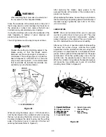
Page 38: ...m lever is spring loaded Release it slowly 2 Lower the tractor implement lift handle to its lowest setting adjust gauge wheels if necessary Disengage the deck idler arm lever from its stop bracket and release the spring tension by rotating the lever out and rearward Refer to Figure 39 Figure 39 3 Remove the rearward end of the PTO belt from the upper pulley of the deck center double pulley Refer t...

Page 39: ...mplement lift handle to its highest setting Slide the mower deck forward so the front lift rod rests to the rear of and free of the front roller bracket slots of the deck Refer to Figure 45 Figure 45 8 Raise the front lift rod upward and slide the mower deck rearward Lower the front lift rod so it rests on the front roller bracket of the deck forward of the slots Refer to Figure 46 Figure 46 9 Fro...

Page 40: ...e the key from the switch Disconnect the spark plug wire for additional safety WARNING When handling the mower deck be careful not to cut yourself on the sharp blades 1 Position the tractor and mower deck on a firm level surface CAUTION To avoid possible equipment damage make sure that the tractor implement lift handle is raised to its highest setting before sliding the deck under the tractor 2 Re...

Page 41: ... 52 Figure 51 Figure 52 5 While holding the front lift rod up slide the mower deck forward until the rod aligns with both front roller bracket slots Lower the lift rod into the front roller bracket slots and slide the deck rearward to engage the lift rod fully forward in the slots of the deck front roller bracket Refer to Figure 53 Figure 53 6 If not already done pull the deck support pins outward...

Page 42: ... fully extended through the lift links to prevent the mower deck from disengaging the lift links while mowing WARNING The deck idler arm lever is spring loaded Release it slowly 9 Disengage the deck idler arm lever from its stop bracket and release the spring tension by rotating the lever out and rearward Refer to Figure 56 Figure 56 WARNING The exhaust system is HOT To avoid personal injury allow...

Page 43: ... of the belt engages the groove of the upper pulley 14 While holding the belt in position rotate and engage the deck idler arm lever into its stop bracket to provide tension on the PTO belt Refer to Figure 60 15 Connect the spark plug wire Figure 59 Figure 60 C MAINTENANCE CLEANING AND BLADE CARE WARNING Before performing any maintenance place the PTO switch in the OFF position engage the brake pe...

Page 44: ... blades apply grease to the exposed threads at the bottom of the spindle bolts to prevent rust buildup When replacing the blades be sure they are installed so that the wind wings are pointing upward toward the top of the deck housing Tighten the nuts to 90 to 110 ft lbs 122 to 149 N m LUBRICATION NOTE We do not recommend the use of a pressure washer or garden hose to clean your unit They may cause...

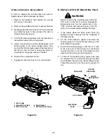
Page 45: ...OF MULCHING PLUG WARNING Before installing the mulching plug place the PTO switch in the OFF position engage the brake pedal lock turn the ignition key to the OFF position and remove the key from the switch to avoid accidental starting and injury 1 If the mower deck has been used clean any buildup of grass clippings from the underside of the deck housing 2 Lift the chute deflector upward and inser...

Page 46: ... from the tank by disconnecting the fuel line from the in line fuel filter near the engine b Reconnect the fuel line and run the engine un til it starts to falter then use the choke to keep the engine running until all fuel in the carbure tor has been exhausted c Again disconnect the fuel line and drain any remaining gasoline from the system 2 Remove the spark plugs and pour one 1 ounce of engine ...

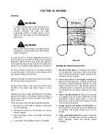
Page 47: ...d time to get a clean cut The following practices will help eliminate streaking 1 Mow the area more often so the grass doesn t get too tall and heavy 2 Operate the tractor at full throttle and slower forward speeds 3 Keep the blades sharp and replace the blades when worn 4 Follow the mowing pattern shown in Figure 65 Figure 65 MOWING WITH MULCHING OPTION 1 Do not cut wet grass For effective mulchi...

Page 48: ...other allied equipment can be purchased from and installed by your authorized Cub Cadet dealer The tractor is used for so many different types of work and because it is called on to operate under so many different conditions a variety or equipment is available to adapt it to the requirements of the user Refer to the attachment guide for a complete description of equipment and required components t...

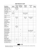
Page 49: ... 5 hours More often under dirty conditions X Check transmission oil level X Replace transmission oil filter After first 10 hours X After first 50 hours X Every 100 hours thereafter X Clean re oil foam air precleaner X Check battery terminals and case X Grease front axle pivot bolt X Grease steering knuckles X Retorque rear wheel lug nuts After first 10 hours X Clean cooling fins external surfaces ...

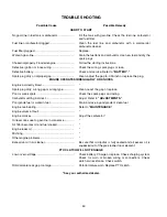
Page 50: ...orrectly timed Spark plug dirty wrong gap or wrong type Clean reset the gap or replace Poor or weak spark Check the spark plugs and wiring Carburetor setting incorrect Adjust Refer to ADJUSTMENTS Poor grade fuel or water in fuel Drain and use a good grade of clean fuel Engine overheating Refer to MAINTENANCE Engine valves at fault Engine smokes Adjust the carburetor Oil level rises due to gasoline...

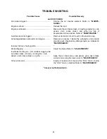
Page 51: ...kage between carburetor and engine Remove air cleaner Tighten the carburetor and manifold mounting nuts Replace any damaged parts as indicated in MAINTENANCE Incorrect timing or faulty ignition Brake dragging Adjust the brake Refer to ADJUSTMENTS Insufficient cooling air dirt or debris clogging the air intake screen shrouds cooling fins side panels dash intake screen or grille Keep the air intake ...

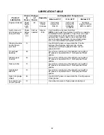
Page 52: ...rive System Fluid Plus Steering knuckles and front axle pivot bolt 10 Use 251H EP grease or equivalent No 2 multe purpose lithium grease and apply two strokes minimum or sufficient grease to flush out old grease and dirt Front wheel bearings 30 Two strokes minimum of the lubricator using 251H EP grease or equivalent No 2 multi purpose lithium grease Steering gear housing 30 Two strokes minimum of ...

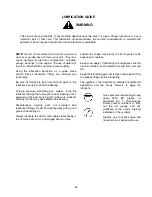
Page 53: ...of each bearing until it emerges at the end carrying with it the worn lubricant and any dirt that may have entered the bearing Miscellaneous working parts not provided with lubrication fittings should be oiled regularly with a good grade of lubricating oil Always lubricate the tractor thoroughly before taking it to a remote location for a prolonged period of time Lubricant is cheap Use plenty of i...

Page 54: ...grease or an equivalent No 2 multi purpose lithium grease and apply 2 strokes minimum or sufficient grease to flush out old grease and dirt 8 Spindle belt idler arm Use 251H EP grease or an equivalent No 2 multi purpose lithium grease and apply 2 strokes minimum or sufficient grease to flush out old grease and dirt After Every 30 Hours of Operation 9 Front wheel bearings Two or three strokes minim...

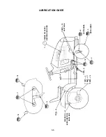
Page 55: ...5 LUBRICATION GUIDE 10 10 30 10 10 30 10 10 100 10 LEFT SIDE BOTH SIDES BOTH SIDES CHECK OIL LEVEL BEFORE EACH USE CHECK OIL LEVEL BEFORE EACH USE 10 50 100 50 50 5 10 9 3 12 6 2 6 8 13 13 7 6 14 11 4 1 ...

Page 56: ...Ignition Spark Plug Gap Cub Cadet No 759 3336 B S Vanguard 16 0 HP 2 2 68 in 2 60 in 29 3 1200 RPM 3600 RPM 3350 RPM 004 006 in 004 006 in Battery 030 in ELECTRICAL SYSTEM System Voltage Battery Alternator Fuse auto type Head Lamp Bulb 12 volt neg ground 725 1706 15 amp regulated 25 amp 725 0963 BRAKES Internal expanding TIRE SIZES Front Rear 15 x 6 6 20 x 9 8 DIMENSIONS Tread Front with 15 x 6 6 ...

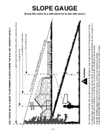
Page 57: ...OU MAY NOT OPERATE SAFELY WARNING Do not mow on inclines with a slope in excess of 15 degrees a rise of approximately 2 1 2 feet every 10 feet A riding mower could overturn and cause serious injury If operating a walk behind mower on such a slope it is extremely difficult to maintain your footing and you could slip resulting in serious injury Operate RIDING mowers up and down slopes never across t...

Page 58: ...ck wheels seats snow thrower skid shoes shave plates and tires c CUB CADET does not extend any warranty for products sold or exported outside of the United States of America its possessions and territories except those sold through CUB CADET S authorized channels of export distribution No implied warranty including any implied warranty of merchantability or fitness for a particular purpose applies...

Page 59: ...ed or otherwise tampered with HOW TO OBTAIN SERVICE Warranty service is available WITH PROOF OF PURCHASE THROUGH YOUR LOCAL AUTHORIZED CUB CADET DEALER To locate the dealer in your area please check for a listing in the Yellow Pages or contact CUB CADET by calling 1 800 528 1009 or writing to P O Box 368023 Cleveland Ohio 44136 9723 This limited warranty does not provide coverage in the following ...

Page 60: ...cleaner BS 272490 Engine Oil Filter Requirements Part No Change every 50 hours BS 492932 Gap Requirements Part No 030 inch gap 759 3336 Oil Filter Requirements Part No Change every 100 hours 923 3014 Transmission Oil Requirements approx 6 qts Part No Check before each use 1 quart 1 gallon 737 3120 737 3121 Deck Blade Belt Tractor to Deck Belt Model Part No Model Part No 42 Deck 954 3073 42 Deck 95...

Reviews: