13
2-12 Hinge Kit Assembly Installation
Assemble the hinge kit as shown in Figure 2-12, using
(2) 5/16”-18 x 1” HHCS P#(K1154), (3) 5/16”-18 nylon
flange locknuts P#(K2516), (5) 1/4” flat washers
P#(K0037) and (2) swing arm brackets P#(ZT-0004).
Place (1) vinyl cap P#(J0289) on the end of the hex bolts
as shown in Figure 2-12. Leave the nuts loose enough to
allow fluid movement of the top when opening and
closing. When opened, the top should rest on the middle
joint of the hinge allowing it to remain up.
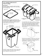
2-11 Top Assembly To Upper Frame
Assembly Installation
Position the top assembly P#(A1139) above the upper
frame assembly as shown in Figure 2-11. Fasten the top
assembly to the upper frame assembly using (2) 5/16”-
18 x 2-1/2” HHCS P#(K0125) and (2) 5/16”-18 nylon
flange locknuts P#(K2516). Leave the locknuts slightly
loose, to allow the top assembly to open and close
easily. Refer to Figure 2-11 for hardware location.
ZT-0004
K2516
K0037
K1154
J0289
Top Assembly
Upper Frame
Assembly
(2) 5/16-18 x 2-1/2” HHCS
(2) 5/16”-18 Nylon Flange
Locknuts
Figure 2-11
Figure 2-12
Summary of Contents for 21131508
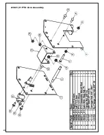
Page 20: ...20 A1841_01 PTO Arm Assembly ...
Page 21: ...21 A1941_01 PTO Base Assembly Exploded Parts View ...
Page 22: ...22 A1941_01 PTO Base Assembly Exploded Parts List ...
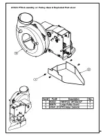
Page 23: ...23 A1623 PTO Assembly w Pulley Guard Exploded Parts List ...
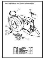
Page 24: ...24 A1821 PTO Assembly w Safety Interlock Exploded Parts List ...
Page 25: ...25 ...
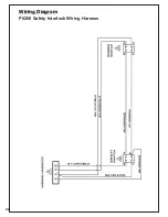
Page 26: ...26 Wiring Diagram P0208 Safety Interlock Wiring Harness ...
Page 30: ...30 ...
Page 31: ...31 NOTES ...


