


86
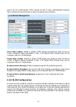
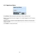
Digital Input-1:
The status of whether the alarm for Digital Input-1 has been triggered.
Power A:
The status of whether the alarm for Power A has been triggered.
Power B:
The status of whether the alarm for Power B has been triggered.
Slot Number:
The status of whether the alarm for slots has been triggered.
Tp/Fx Port:
The status of whether the alarm for Tp/Fx ports has been triggered.
NOTE
:
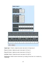
Remember to enable the desired Digital Output Event. Otherwise, the alarm status
always shows OFF.
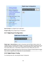
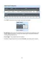
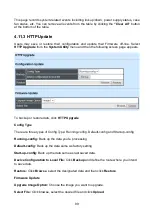
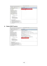
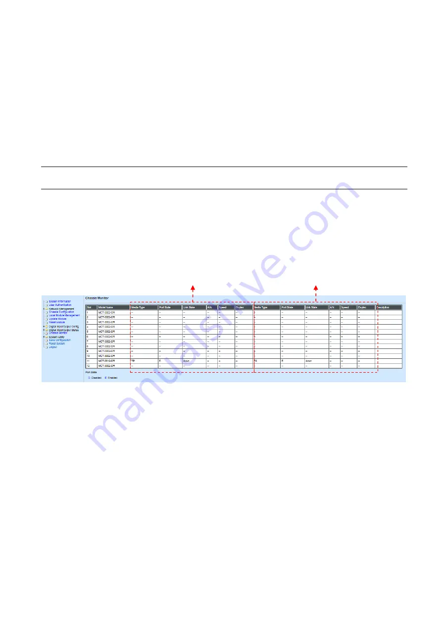
4.10 Chassis Monitor
Select
Chassis Monitor
from the
Main Menu
, then the following screen page appears. This
is intended to show overall status of converters.
The Chassis Monitor is mainly divided into two sections as below. The left squared section is
for TP port while the right is for fiber port.
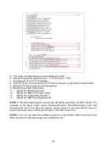
1. Model Name:
Display the name of connected unit.
2. Media Type:
TP (copper, 10/100Base-T, RJ-45) and FX (fiber).
3. Port State:
View-only field that shows traffic is Disabled or Forwarding.
4. Link State:
View-only field that shows the link is up or down.
5. A/N:
View-only field that shows Auto-negotiation is on or off.
6. Speed:
View-only field that shows the port speed.
7. Duplex:
View-only field that shows the duplex mode is half or full.
8. Description:
Specify the appropriate brief description for the slide-in converter module.
For TP Port
For Fiber Port


