background image

2

EN

Logika - use and maintenance guide

5/16

page

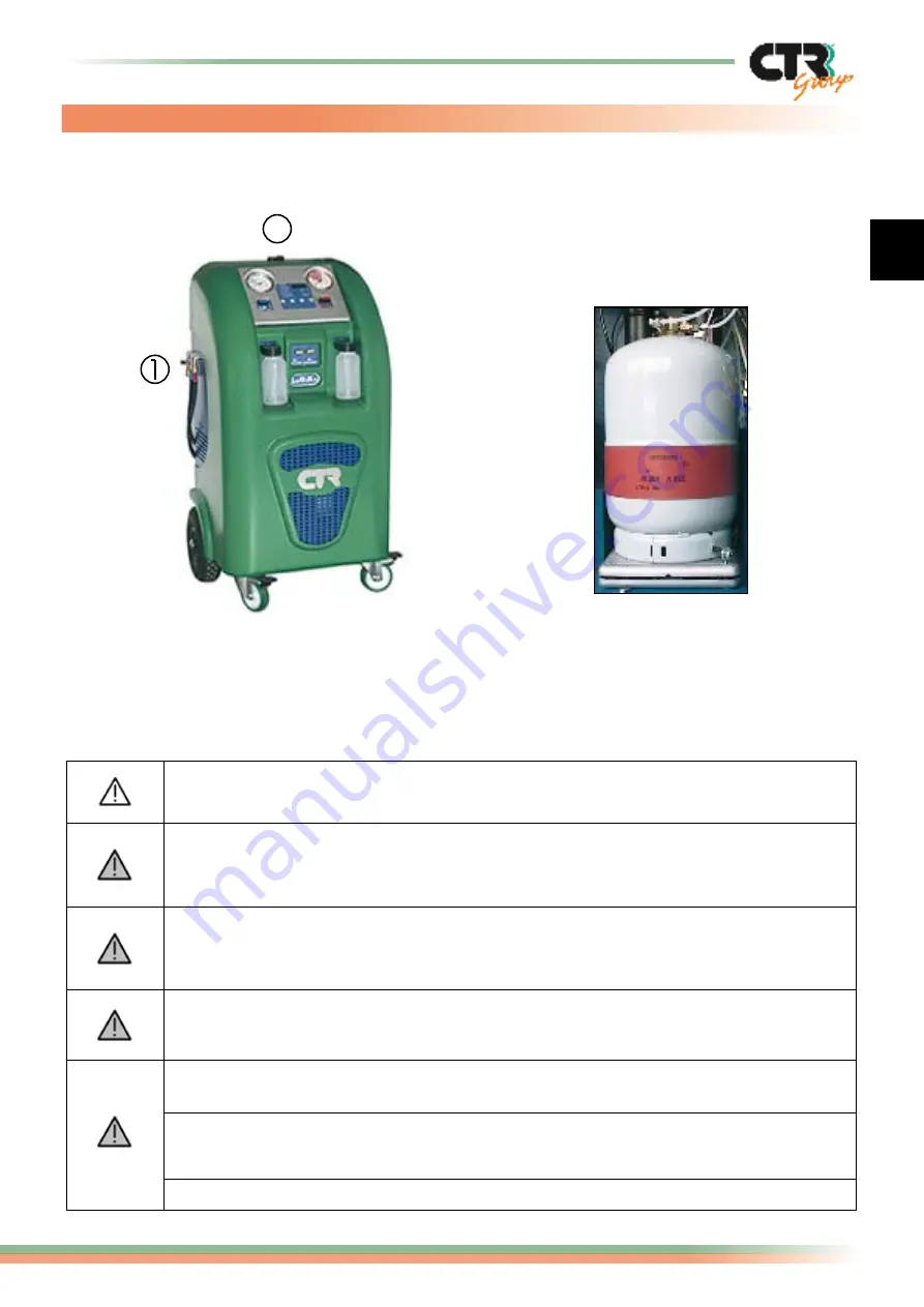
This figure indicates the areas on the machine where there may be a safety hazard during 

operations:

When the machine is operating, check the level of oil in the two tanks making 

sure that it does not overflow.

We remind you that maintenance and repair carried out by not qualified staff 

change the standard of security of the machine and expose the worker to serious 

risks.

NEVER

 disconnect the 

HP

 and 

LP

 hoses, unless expressly stated in this guide. 

Do not manually action the manual filling valves during normal operating phases 

unless expressly stated in the instructions.

Always wait some minutes after having switched off the machine to allow the 

system to be correctly reset (temperature and pressure).

In no case should the operator use combustible or flammable liquids or detergents 

for cleaning the machine. 
During maintenance work do not contaminate the environment with eventual 

residual  waste  products  and  always  follow  the  prescribed  directives  in  force 

regarding disposal.

NEVER

 disassemble the cylinder.

The machine is delivered with 

the cylinder correctly positioned 

in its seating on the weighing 

scale and already fixed with 

brackets (n. 2) for this purpose. 

3.  Warning

1)

  Area where refrigerant may be

     ejected.

2)

  Components carrying live current.

Summary of Contents for Logika

Page 1: ...LOGIKA USE AND MAINTENANCE GUIDE...

Page 2: ...t the machine is used for a purpose other than that for which it was intended or is tampered with by persons not authorised by our company or in any case using non compliant methods or parts The Compa...

Page 3: ...ilters 15 15 3 Oil containers 15 4 Charging and service hoses 15 5 Spare parts 16 Labels SYMBOLS KEY DANGER indicates situations or problems that can be a safety risk and an accident or life threateni...

Page 4: ...G functions if pre set for this purpose or should the quantity of gas exceed the set limits Electronic precision scale for weighing of oil injection it can weigh up to a maximum of 500 grams with a ma...

Page 5: ...V 220 240 220 240 Supply frequency Hz 50 50 Max absorbed current A 5 0 5 0 Coupling diameter on vehicle Low Pressure LP mm 11 13 Coupling diameter on vehicle High pressure HP mm 11 16 Max operating te...

Page 6: ...ng normal operating phases unless expressly stated in the instructions Always wait some minutes after having switched off the machine to allow the system to be correctly reset temperature and pressure...

Page 7: ...is equipped with the prescribed safety devices in accordance with the relevant codes in force differential circuit breaker mechanism and earthing grounding system We advise you to follow the instruct...

Page 8: ...tion 4 High pressure gauge 30 bar 11 Ref Service coupling 5 LP valve low pressure 12 Low pressure connection Blue 6 HP valve high pressure 13 High pressure connection Red 7 Oil injection tank connecti...

Page 9: ...in vacuum control cycle E6 Insufficient quantity of refrigerant for programmed charge E7 Refrigerant oil charge time expired E9 Insufficient quantity of oil injection Possible error codes 7 Menu struc...

Page 10: ...Terminated the pressure in the A C system the display visualizes T200 seconds for eventual refrigerant still blocked in the system in the form of micro frozen granules of oil and humidity At the end...

Page 11: ...ys Press the OK key to proceed with the vacuum function If the pre set time doesn t decrease after 10 minutes the function will stop and the error code E4 will appear time to achieve vacuum expired Ch...

Page 12: ...nd the led START lights on to start the charging operation fig 3 During the oil and gas charging the display visualizes the grams with a margin of error of 10 gr Oil will be charged only after the vac...

Page 13: ...vacuum phase If at the end of this phase it is not possible to close the LP valve once the charging operation has come to an end wait for three minutes before starting the A C system or in case of on...

Page 14: ...ammed for recovery E2 Recovery time expired E3 Pressure present in the system at the start or during the vacuum cycle E4 Time to achieve vacuum expired E5 Leaks found in vacuum control cycle E6 Insuff...

Page 15: ...gas left in the hose Check the oil level in the vacuum pump every three months Change the oil in the vacuum pump every six months even when the unit is not used regularly Check the calibration of the...

Page 16: ...al sheets on request The machine is supplied with connecting hoses to the A C plant of length equal to 1800 mm Should the standard tubing not be of sufficient length for your requirements tubing lengt...

Page 17: ...by CTR Group S p A all rights reserved CTR Group s p a Via T ed E Manzini 9 43100 Parma Italy Tel 39 0521 957611 Fax 39 0521 957677 internet http www ctrgroup it e mail ctrgroup ctrgroup it...

Reviews: