background image

Repair and Service:

Always use CTD factory authorized replacement parts and consult factory before making any repairs or adjust-

ments which may be unclear.

Fence Alignment and 45

 Angle Adjustment of Blades:

All machines are preset at the factory for perfect 90

 and 45

 mitre cuts.  If any adjustments are necessary:

1. Check alignment of fences—left to right, as shown in Diagram “B“ on Page No. 5.  Use a two foot steel

scale or quality precision straight edge and lay flat on table base.  Butt edge against  inside fence  and

outside fence.  Touch the outside corner of  the straight edge.  If  one side of the straight edge pulls away

from the fence, then the outside fence is not in alignment with the inside fence.

2. Loosen 3/8-16 lock nut on both fence brackets.  Clean all surfaces of dirt or dust, and re-assemble as

before.

3. Re-align inside fence to outside fence with your straight edge.  Once you are sure both fences are in

alignment, you now have a reference point to check your 45

 mitre.

If  adjustments of  the 45

 mitre settings are necessary, you will need a precision draftsman’s triangle. Check the 45

mitre by placing the triangle against the inside fence and the plate of the blade, below or in between the gullets or

teeth of a Carbide Blade.  Touch the triangle against the steel plate of the blade—not against the tips.  If an adjustment

is necessary:

A. Loosen the lock nut on the adjusting screw (3/8-16 Hex Cap Screw), that locks through the 45

Stop Key, P/N 2DM29.

B. Adjust 3/8-16 screw until blade plate aligns perfectly with precision triangle.  Now, tighten the screw

and nut.  It is not necessary to move the 45

 stop key.

Irregular Mitres:

Irregular mitre cuts are almost always caused by out-of-square material.  Check your material with a 90

 square

and a straight edge.  Material that has a high spot on the bottom will move, or roll forward as it is being cut (even

with pneumatic hold down clamps), thereby causing the blade to cut more on the inside of the moulding than the

outside.  Another cause of irregular mitre cuts is too thin a blade plate thickness.  Blade plate thickness should be

.100 to .110 on 12” blades.  Blades will find the easiest avenue to cut through material, and sometimes the blade

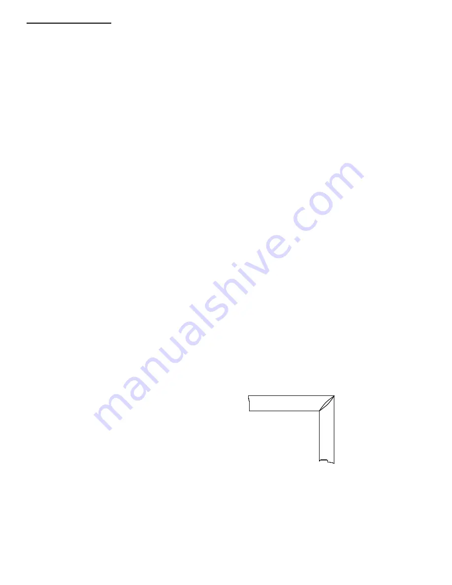
plate will distort when cutting heavier sections.  The drawing is an example of a cut  when blade plate is too thin

for the material being cut.

Other Repairs:

See specific sections within the manual for additional information on repairs and maintenance.

-17-

Summary of Contents for DM200R

Page 1: ...ODELS DM200R DM400 05 16 CTD MODEL NO CTD SERIAL NO MANUFACTURE DATE DISTRIBUTOR PURCHASED THROUGH IF ANY CTD MACHINES 2382 East 48th Street Vernon CA 90058 Tele 213 689 4455 FAX 213 689 1255 World Wide Web http www ctdsaw com e mail ctdsaw ctdsaw com ...

Page 2: ...indle Diagrams 32 DM400 Spindle Installation Prosedure 33 Pivot Shaft Diagrams 34 Warranty Guarantee 34 Machine Requirements MODEL NO _____________ SERIAL NO ________________ Cutting Capacities Model DM200R 90 Cutting 2 51mm high x 7 3 4 197mm wide 3 3 4 95mm high x 3 3 4 95mm wide 45 Cutting 1 1 2 38mm high x 4 7 8 123mm wide 2 57mm high x 4 1 4 108mm wide 3 1 2 89mm high x 3 1 2 89mm wide DM400 ...

Page 3: ... DM400 8 H P 3 Phase 460 Volt 10 amps each motor 40 amp DM400 10 H P 3 Phase 230 Volt 26 amps each motor 60 amp DM400 10 H P 3 Phase 460 Volt 13 amps each motor 40 amp DM400 15 H P 3 Phase 230 Volt 34 amps each motor 60 amp DM400 15 H P 3 Phase 460 Volt 17 amps each motor 60 amp Breaker needed if both motors on the same circuit breaker Cutting Tool Requirements Heavy rigid plate blades 12 blades 1...

Page 4: ...n hand with a rag covering sharp tips or lower blade into a piece of wood so it will not rotate Push down with wrench on spindle nut Remove spindle nut and outer flange 2 Place blade on spindle with tips pointing down Make sure slinger inner flange and blade surface are CLEAN before putting blade on spindle This is a critical surface and is ground within 0005 flatness Any debris or dust will wear ...

Page 5: ...ry important that long work be supported in the center to avoid springing or vibration of the work as it is being cut If the work is allowed to sag inaccurate cuts will be made This problem is eliminated by the use of the Center Work Support accessory item CWS which may be purchased along with the machine 3 The fences on both heads must be in good alignment with each other This is easily accomplis...

Page 6: ...to the top of each Magnetic Starter Use dust proof connectors if available Single Phase Motor Replacement Connect leads to L1 line 1 and L2 for single phase motors See Wiring Diagram for Single Phase Motors on Page No 7 Green ground wire must be grounded to enclosure If using type SO wire and plug use a romex connector through starter box and a grounded plug Be sure to check rotation The blade mus...

Page 7: ...er maintenance 11 Keep work area clean Cluttered areas benches and slippery floors invite accidents 12 Avoid dangerous environments Keep work area well illuminated 13 Wear ear protection if exposed to long periods of very noisy shop operations 14 Keep visitors away All visitors should be kept a safe distance from work area 15 Do not force the machine The saw will do a better job and be safer to op...

Page 8: ...et 5 8 in front of the centerline then when changing mitre angle the length dimensionat 45and90degrees will staythesame Noadjustment to measuringscalewill be necessary However anyother angles require slight adjustment of the scale Note The scrap drop off piece needs to be backed up by the rear outside fence If thetrimmed cut offmaterial is not supportedbytherearoutsidefence thecut offpiececan catc...

Page 9: ...0 2 ManuallyrotateTop Base to desired degree setting aligning angle mark and pointer 45 90 stops are provided 3 Tighten lock down bolts Saws are designedto mitre toward each other as shown inDiagram B Ifyou have purchased amachine with angular adjustment in theopposite direction it is necessaryto remove lock down bolts and reposition inadditional tapped holes provided Also the inside fences mayhav...

Page 10: ...ld material down against the table base are provided as a standard feature on all double end trim saws For odd shapes and profiles additional clamping or fixturing may be necessary Horizontal Clamps that push the material back against fence can be provided as an optional accessory The Horizontal Clamps mount to the Center Supports thatholdtheVerticalClampsfor theDM400 Theymountto special insidesup...

Page 11: ... not attempt to raise the blade out of the material Instead tap the piece down on both sides of the blade with light pressure until the piece has freed the blade Cutting Wood While wood is generally soft and simpler to cut than aluminum it requires that the material be held in place as the blades pass through the material CTD suggests using a Carbide Blade with an Alternate Top Bevel AT for lighte...

Page 12: ...ertical Clamps for this application Additional toolingmayberequired Special carbideblades areavailableforcuttingplastics AngularAdjustment in Opposite direction for CTD Models DM200R or DM400 1 Remove90 degreestop p n2DM29 from keywaybyremovingbolt lifting awayand settingaside 2 MoveVertical ClampAssemblyon inside fence bracket to center work support by see diagram on bottom of page 10oftheinstruc...

Page 13: ...shown in the Air Circuit Piping Diagram on the following page The system operates using a Two Hand Anti Tie Down Control for safety Included with the Air Pneumatic System arethe maindriveCylinders andValves anAirFilter Regulator and twoVertical Pneumatic Clamps TheVertical Clamps must be actuated prior to the activation of the saw heads via a Foot Valve P N B3P53E which in turn energizes theTwo Ha...

Page 14: ...e speed of saw down B3P73 B3P73 P1 2 2 4 Way Spring Return Valve main control valve B3P50 B3P50 LV1 1 3 Way Normally Open N O Valve controls accessory items SM and VC B3P86 B3P86 S1 1 Shuttle Valve B3P63 B3P63 2 Upstroke Valve speed of saw up 2B7S15 157P73 2 Rubber Bumper B3P154 B3P154 1 FR Unit with Auto Drain 200M06 N A 2 Motor Mount Plate 200M80 4BM80 2 Cylinder Support Studs 200M82 2B3P31 2 Cy...

Page 15: ... This collects and then releases foreign matter and condensation collected by the air filter 2 The Pressure Regulator which is located on top of the air filter controls the amount of air pressure allowed into the system An operating pressure of 75 PSI 5 4 kg cm2 is required This is set at the factory AirFilter Regulator Trouble Shooting the Pneumatic System for Downfeed of Saw Head If the Air Feed...

Page 16: ... main drive Cylinder P N 2B3P05 or P N B3P306 Adjust as required for best finish The Upstroke Control Valve P N B3P63 is located in port No 5 of the main control Valve P N B3P73 Simply loosen nut on machine screw 10 32 thread and adjust IN to slow down or OUT to speed up Preventative Maintenance The CTD Double End Trim Saws are relatively easy machines to operate and maintain Following is a weekly...

Page 17: ...gle against the inside fence and the plate of the blade below or in between the gullets or teeth of a Carbide Blade Touch the triangle against the steel plate of the blade not against the tips If an adjustment is necessary A Loosen the lock nut on the adjusting screw 3 8 16 Hex Cap Screw that locks through the 45 Stop Key P N 2DM29 B Adjust 3 8 16 screw until blade plate aligns perfectly with prec...

Page 18: ... 18 ...

Page 19: ... 19 ...

Page 20: ...DM200 Base Assembly Exploded View Right Side Shown Left Opposite 20 ...

Page 21: ...DM200 Base Assembly Parts List 21 ...

Page 22: ... 22 ...

Page 23: ... 23 ...

Page 24: ...400S Blade Guard and Stand Exploded View Model M516 Shown Right Side Shown Left Opposite 24 ...

Page 25: ...400S Blade Guard and Stand Parts List Model M516 Shown 25 ...

Page 26: ... 26 ...

Page 27: ...400S Base Parts List Model M516 Shown 27 ...

Page 28: ... 28 ...

Page 29: ...Parts list 29 ...

Page 30: ... 30 ...

Page 31: ...led in exactly the same position in relation to each other Use an arbor press or pulley puller H Press off slinger and bearing from spindle I Press new bearing on to spindle making sure spindle is square to the bore J Replace slinger as above making sure scored lines match K The face of the slinger must be checked to make sure the face next to the blade is running true If it is not running true it...

Page 32: ...ght Hand Saw facing it from the front Belt guard is on right side blade guard is on the left side DM200R SPINDLEASSEMBLY Part No 4BM40X SpindleAssembly consists of following parts assembled together with the face of the slinger ground A Spindle No 1 Note Items 1 4 1 each 5 6 7 8 9 13 are included in B Bearings No 4 1 each Spindle Assembly but are shipped loose C Slinger No 3 D Flange No 2 400X SPI...

Page 33: ... slip out from pulley side Normally it is the pulley side bearing that fails first If replacement Spindle Assembly was purchased go to G D If the bearing on the blade side must be replaced an arbor press must be used to disassemble the bearing and slinger from the spindle Great care must be used in disassembly or the spindle will be scored and stripped by the slinger Before pressing apart scribe a...

Page 34: ...it customer s account for the replacement cost All motors are shipped FOB CTD Los Angeles CA plant Guarantee CTD warrants that their cut off machines and accessories are free from defect of material workmanship and title and are of the kind of quality indicated and described in applicable specifications The foregoing warranty is exclusive and in lieu of all other warranties whether written or oral...

Page 35: ......

Reviews: