Chapter 3. Operation
30
3.4.10
E1/T1
Mode
Configuration
(RJ45
models
only)
The
multiplexer
uses
a
software
programmable
LIU
(line
interface
unit)
that
can
be
configure
for
E1
or
T1
mode.
For
the
BNC
model
multiplexers,
the
mode
is
fixed
for
E1,
75
ohm
as
the
transmission
media
is
coaxial
cable
and
therefore
will
always
be
E1,
75
ohm.
However,
for
the
RJ
‐
45
models,
the
multiplexer
can
have
all
ports
configured
for
E1
75
ohms,
E1
120
ohms
or
T1
(DS1)
100
ohms.
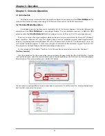
The
setting
is
made
by
choosing
the
'S'
item
and
then
selecting
the
desired
mode.
(Remember
to
'save'
the
settings
under
the
Device
menu.)
3.4.11
E1
(T1)
Configuration
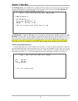
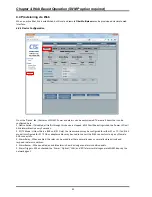
The
menu
screen
is
broken
into
two
parts,
the
informational
part
and
the
configuration
part.
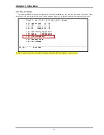
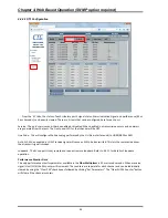
Information
The
current
E1/T1
mode
for
the
device
is
displayed
(E1,
RJ45,
120
ohm
in
the
below
example)
along
with
a
running
count
of
UAS
(unavailable
seconds)
count.
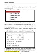
The
status
of
RX
Loss
of
Signal
will
be
"Normal"
when
E1
(T1)
signal
is
present.
If
no
signal
is
present,
the
RX
Loss
of
Signal
will
be
indicated.
LoS
indicates
that
the
signal
from
the
connected
E1
(T1)
device
is
not
being
received.
It
could
be
a
very
simple
issue
with
cable
not
connected
or
possibly
wrong
twisted
pair
wiring.
When
a
connected
E1
(T1)
device
no
longer
receives
E1
(T1)
signal
from
the
multiplexer,
it
should
issue
AIS
(alarm
indication
signal)
on
the
E1
(T1)
path
back
to
the
multiplexer.
The
alarm
AIS
Detected
means
we
are
able
to
receive
E1
(T1)
from
the
connected
device,
but
for
some
reason
that
device
is
not
receiving
our
signal.
Again,
this
is
probably
a
cabling
issue.
Line
Code
Violation
,
LCV
for
short,
or
Bi
‐
Polar
Violation,
BPV
for
short,
are
indications
of
an
electrical
problem
at
Layer
1.
LCV
or
BPV
will
either
be
caused
by
noise
or
interference
on
the
E1
(T1)
cabling
or
it
could
indicate
a
hardware
failure
of
the
LIU
(line
Interface
Unit
i.e.,
the
E1/T1
transceiver
chip).
TX
Driver
Failure
is
an
indication
of
hardware
failure
of
the
LIU
(line
Interface
Unit
i.e.,
the
E1/T1
transceiver
chip).
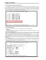
[Local ] Ver:[1.100-1.001-0.000-1.000] [Alarm]
< 1 > E1 Channel 01 Link [UP ]
< 2 > E1 Channel 02 Link [UP ]
< 3 > E1 Channel 03 Link [UP ]
< 4 > E1 Channel 04 Link [Down]
< 5 > E1 Channel 05 Link [Down]
< 6 > E1 Channel 06 Link [Down]
< 7 > E1 Channel 07 Link [Down]
< 8 > E1 Channel 08 Link [Down]
< A > All Channel Configuration
[ S ] Set to E1/T1 mode [E1 120 ohm]
[ ESC ] Go to previous menu.
------------------------------------------------------------------------------
<0> E1 75 ohm <1> E1 120 ohm <2> T1 100 ohm <Esc> Exit
[Local ] Ver:[1.000-1.000-0.000-0.000] [Alarm]
<< E1 Port 01 Information and Configuration >>
< Information >
Mode: E1 [RJ45 ] 120 ohm Performance [ 0]
Rx Loss Signal Detect [Normal ]
AIS Detect [Normal ]
Line Code Violation [Normal ]
TX Driver Failure [Normal ]
< Configuration >
< 1 > Service [Enable ]
< 2 > Line Code [HDB3/B8ZS]
< 3 > Auto AIS [Disable]
< 4 > Clear Performance Counter
< 5 > Loopback Test [Disable]
[ ESC ] Go to previous menu. Please select an item.
Summary of Contents for FMUX160
Page 2: ......
Page 34: ...Chapter 3 Operation 34 This page was left blank intentionally ...
Page 54: ......
Page 55: ......
Page 56: ......


