background image

Page 4   


GaugeCal

XP

 Service Instruction Sheet

C R Y S T A L


engineering corporation

17

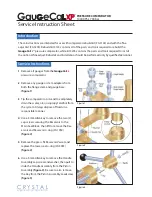
  Use a 5mm Allen key to remove the four (4) 

cap screws holding the rear Gauge Base to 
the top of the Manifold Block, then lift the 
Gauge Base and its o-ring (

PN 

3130) from the 

Manifold Block 

(figure 12)

.

18

  Remove the forward Gauge Base by follow-

ing the procedure outlined in step 16.

If the comparator is fitted with an optional 
Fine Adjust Kit, continue to step 19. If not, 
you may skip ahead to step 25.

Note:

 A comparator without the Fine Adjust 

option is instead fitted with an Accessory 
Cap, plus an o-ring that should be replaced. 
The screws for the plate will require a 4mm 
Allen key to remove. Screws included with 
older Fine Adjust Kits will require a 5mm key, 
while those included with recent, redesigned 
kits will require a 4mm key.

19

  Use either a 4- or 5mm Allen key to remove 

the four (4) cap screws holding the Fine Ad-
just to the side of the Manifold Block, then 
pull the Fine Adjust and its o-ring (

PN 

1734) 

away from the Manifold Block 

(figure 13)

.

20

  Use a 3mm Allen key to loosen the set screw 

inside the Fine Adjust knob, then slide the 
knob off of the piston 

(figure 14)

.

21

  Use a 15mm box wrench to remove the Fine 

Adjust bushing from the body, then slide the 
bushing and its o-ring (

PN 

1959) off of the 

piston 

(figure 15)

.

22

  With the front of the Fine Adjust body facing 

toward you, turn the piston clockwise until 
the piston threads are clear of the hole in the 
back of the Fine Adjust body 

(figure 16)

.

Figure 12

Figure 13

Figure 14

Figure 15

Summary of Contents for GaugeCaLXP

Page 1: ...and gauge base gure 1 3 Tip the comparator on its end to completely drain the water oil or isopropyl alcohol from the system Always dispose of uids in a responsible manner 4 Use a 3mm Allen key to re...

Page 2: ...llen key to remove the three 3 cap screws from the front of the End Block gure 5 10 Carefully pull to slide the End Block and Piston Assembly from the Manifold Block and Baseplate gure 6 11 Pull to sl...

Page 3: ...ilar sili cone based lubricant must be applied to the grooved surface of the Rod Seal PN 3152 When the Rod Seal is installed its at sur face should face toward the Main Seal Block while its grooved su...

Page 4: ...len key to remove Screws included with older Fine Adjust Kits will require a 5mm key while those included with recent redesigned kits will require a 4mm key 19 Use either a 4 or 5mm Allen key to remov...

Page 5: ...f the comparator is not tted with an optional Fine Adjust remove the second Accessory Cap located on the other side of the Manifold Block Follow the procedure outlined in step 25 27 Clean all of the p...

Page 6: ...129 O ring 6 07mm x 1 78mm 0 239in x 0 070in QTY 1 3130 O ring 21 94mm x 1 78mm 0 864in x 0 070in QTY 2 3150 Backup ring 3131 O ring 21 82mm x 3 53mm 0 859in x 0 139in QTY 1 3132 O ring 15 54mm x 2 62...

Page 7: ...stem and gauge base 2 To completely open the reservoir wind the handle counter clockwise until you feel it stop 3 Securely grip the front of the Baseplate near the end block and lift to tip the GaugeC...

Page 8: ...C R Y S T A L engineering corporation 2005 Crystal Engineering Corporation 708 Fiero Lane Suite 9 San Luis Obispo California 93401 8701 PN 3175 Rev A...

Reviews: