


INTERFACING SOLUTIONS
RVCAD-81M
REAR-VIEW CAMERA INTEGRATION
FOR SELECT AUDI with MMI 3G + 4G
VEHICLES 2012-2014
www.cruxinterfacing.com
Rev. 070615
5
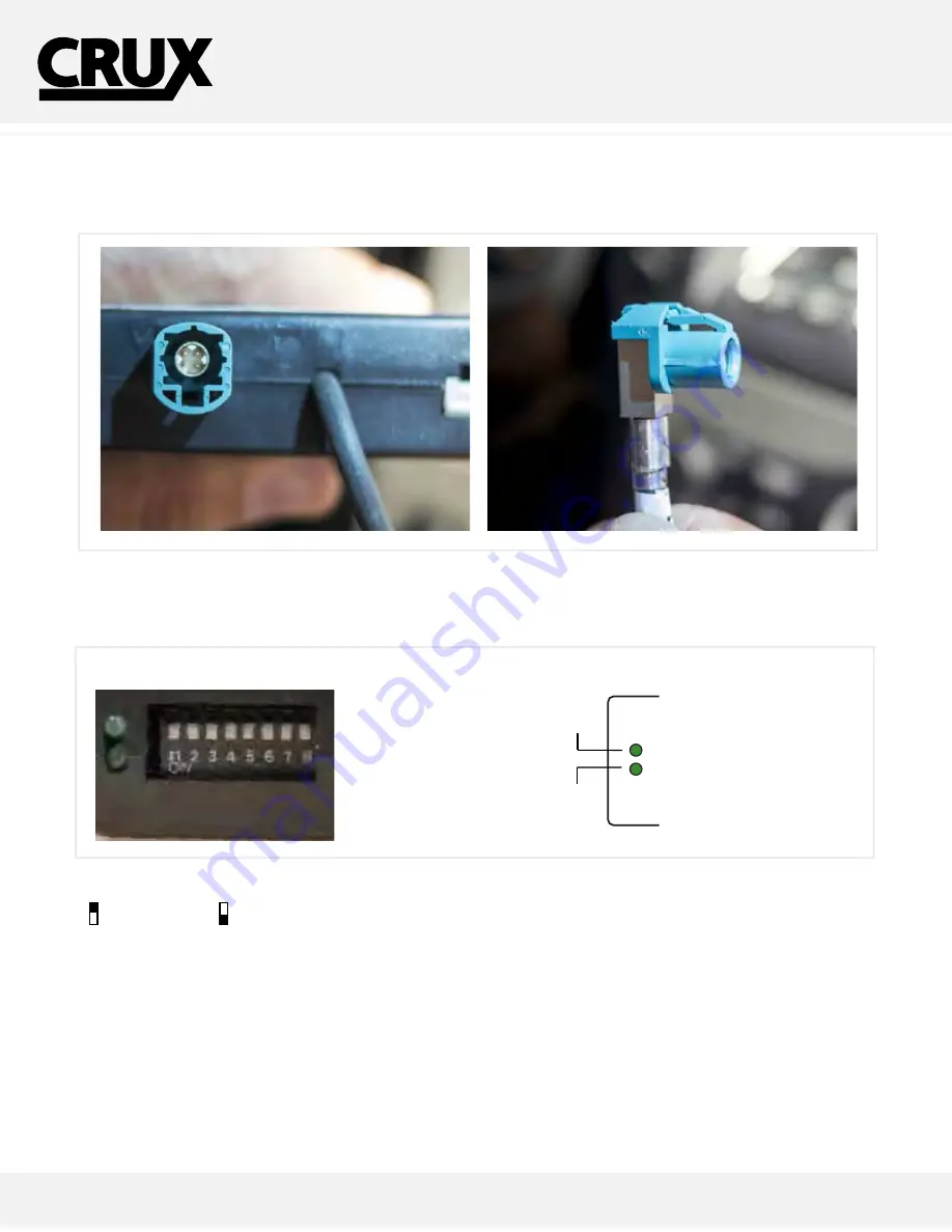
CONNECTING THE LVDS
These steps will help you with installing the LVDS connections on the module.
Step 3
- Connect the factory LVDS to the INPUT on our module, then connect our OUTPUT LVDS connection to the factory display.
Step 4
- After connecting the module, set the proper dip switches to the “ON” position. Make sure to set the AV sources being used to the
“ON” position.
NOTE: The Video In-Motion feature does not require activation. This feature is permanently ON and will not
disturb the navigation GPS performance.
DIP SWITCH DESCRIPTION
IF NOT USING THE INPUT, PLACE TO OFF
DIP 1 =
RGB Input ON = Enable / OFF Disable
DIP 2 =
AV1
ON = Enable / OFF = Disable
DIP 3 =
AV2
ON = Enable / OFF = Disable
DIP 4 =
RGB Input
DIP 5 =
DIP 6 =
DIP 7 =
DIP 8 =
After each change of the DIP switch settings,
we recommend powering down the module,
then restarting the vehicle.
LED INDICATORS
DATALINK LED:
Blinking = BUS Detected.
OFF = Power Down/ Sleep mode.
POWER LED:
ON = Power On
OFF = Power OFF
DIP SWITCHES
LED INDICATORS
UP=OFF
DOWN=ON
VIDEO
(male plug)
4 5 6 7 8
OFF
1 2 3
8-PIN
(male plug)
MULTI
MEDIA
INTER
ON
DATALINK STATUS
POWER STATUS
DAT
POWER S
CAMERA IN
VIDEO 1 & 2
INPUTS
6-PIN
(male plug)
VIDEO
INPUTS
DIP SET
RGB
AUDIO
IN/OUT
BULLET
CAMERA
RED/
POWER 12V
BLACK/
GROUND
CAMERA OUT
INPUT
OUTPUT
ON = VGA Resolution [800 x 480]
OFF = NTSC Resolution [400 (or 480) x 200]
ON = AV4 Video is Selected if Aftermarket Camera is Installed and
Green wire is connected to +12V
OFF = OEM Picture is Selected when Green wire is connected to +12V
Set to ON once for IR programming / Set to ON 5 times for Touch Panel Calibration
Always set to ON (down)
ON = Screen is 400 x 240 resolution for A1, A2, A4, Q5 models
OFF = Screen is 800 x 480 resolution for A6 and Q7 models


