


Crux Interfacing Solutions
6860 Canby Avenue, Suite 116,
Reseda, CA 91335
tel. #: (818) 609-9299
fax #: (818) 996-8188
continued
10.
Connect 8-Pin Molex from the T-Harness
the end of the CAN-BUS module.
11.
Connect the White 6-Pin power
connector and the smaller 8-Pin
connector to the main interface.
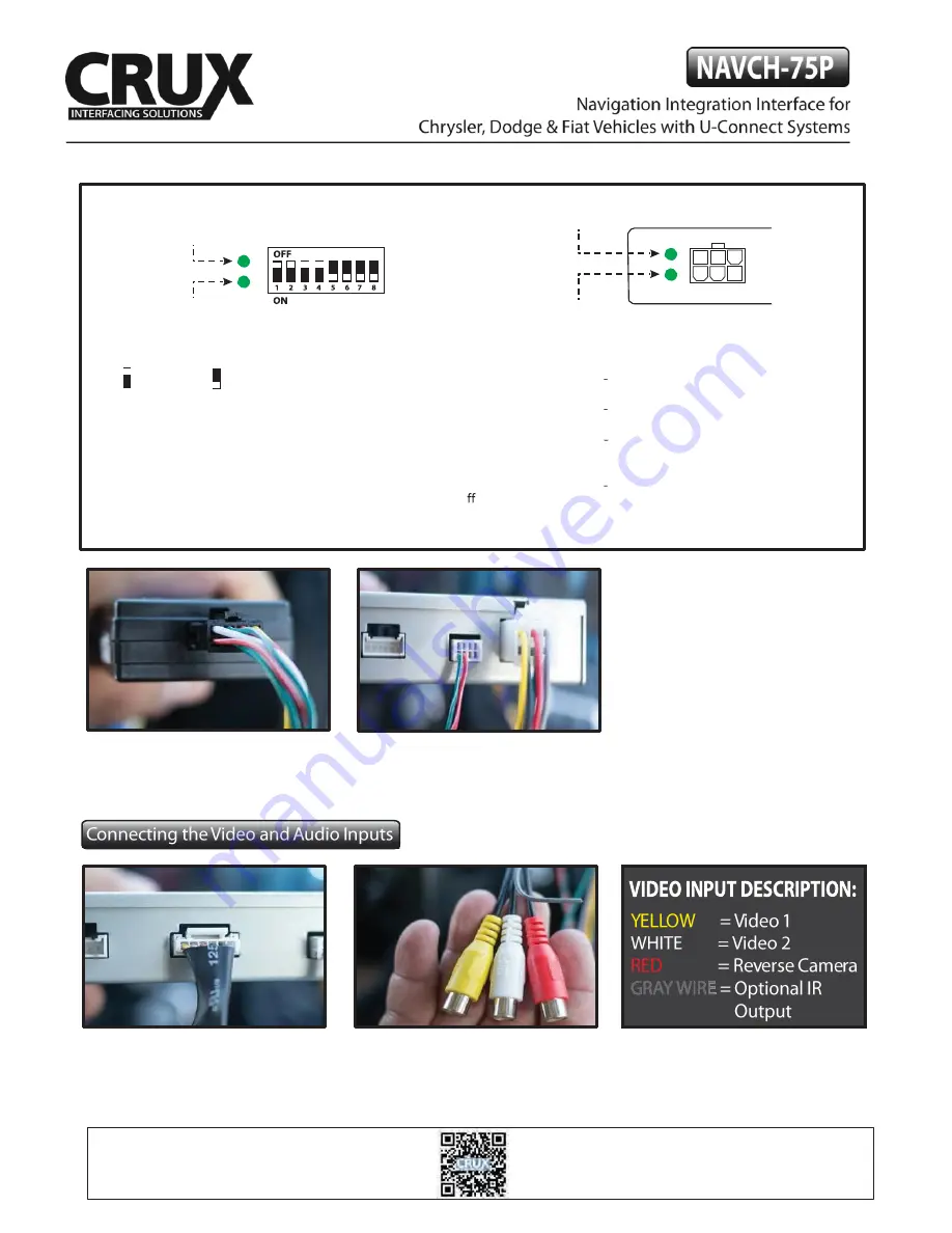
1.
Connect the 6-Pin Video Adaptor to
the main interface module. This allows 2
video inputs plus one Camera input.
2.
Plug the video sources or rear-view
camera to the RCA connectors.
MAIN INTERFACE
MODULE
DATALINK Status
POWER Status
CAN-BUS
Module
POWER Status
DATALINK Status
DIP SWITCH DESCRIPTION
UP = OFF
DOWN = ON
DIP 1 = RGB Enable
DIP 2 = AV1 Enable
DIP 3 = AV2 Enable
DIP 4 = RGB (ON= 480p / OFF= 1080p)
DIP 5 = AV4 Enable / Green Wire
DIP 6 = IR Programming
DIP 7 = Not used
DIP 8 = ON = 8.4”
/ OFF = 4.3”
LED INDICATORS
DATA LINK STATUS:
Blinking = No BUS Detected.
Solid = BUS Recognized.
OFF = Power Down / Sleep Mode.
POWER STATUS:
ON = Power On
OFF = Power O
NOTES:
Before connecting the main module, set
the proper DIP switch to the
‘
ON
’
position.
Make sure to set the AV source being used to
the
‘
ON
’
position.
After each change of the DIP switch settings,
we recommend powering down the module,
then restarting the vehicle.
The Video-In-Motion feature does not require
activation. This feature is permanently ON
and will not disturb the GPS performance.
3 / 6
rev.042817


