


SST Modules
Page 10
Reference Manual
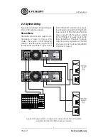
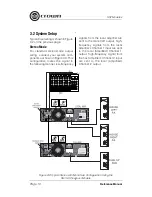
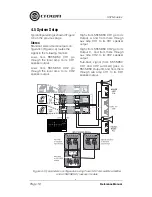
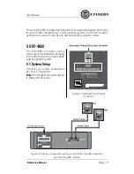
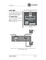
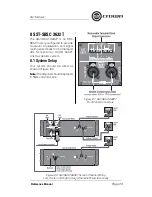
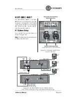
3.2 System Setup
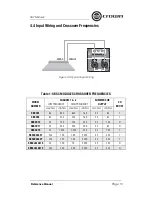
Typical input wiring is shown in Figure
3.2 on the previous page.
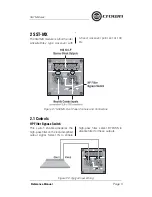
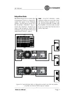
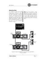
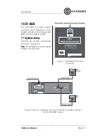
Stereo Mode
For standard stereo-mode output
wiring, connect your system com-
ponents as shown in Figure 3.3. This
confi guration routes the signal in
the following manner: low-frequency
signals from the local amplifi er are
sent to the male XLR output; high-
frequency signals from the local
amplifi er’s Channel 1 input are sent
to the local (amplifi ed) Channel 1
output; high-frequency signal from
the host amplifi er’s Channel 2 input
are sent to the local (amplified)
Channel 2 output.
Figure 3.3 Typical Stereo with Mono Sub Confi guration Using the
SST-SX Crossover Module
Summary of Contents for SST-3632
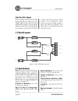
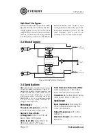
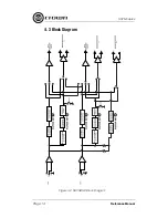
Page 14: ...SST Modules Page 14 Reference Manual Figure 4 2 SST SBSC Block Diagram 4 3 Block Diagram...
Page 32: ......
Page 34: ......


