


14
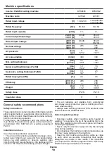
English
23
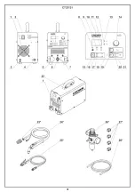
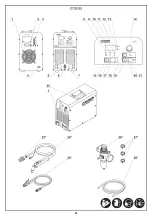
Protective collar *
24
Cutting torch (assembled) *
25
Earth clamp (assembled) *
26
Pressure reducting valve (assembled) *
27
Hose clamp *
28
Hose *
29
Grounding wire *
30
Plug *
31
Connection pipe of pressure reducting valve *
32
Manometer *
33
Bracket *
34
Screw *
35
Mounting nut *
36
Protective cover *
37
Cutting torch body *
38
Nozzle *
39
Diffuser *
40
Electrode *
41
Allen key *
42
Button of torch
43
Cutting torch cable connector nut *
44
Cutting torch control cable connector nut *
45
Valve *
46
Condensate drain button *
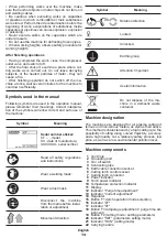
* Optional extra
Not all of the accessories illustrated or described
are included as standard delivery.
Installation and regulation of machine
elements
Before carrying out any works on the machine it
must be disconnected from the mains.
Do not draw up the fastening elements
too tight to avoid damaging the thread.
Mounting / dismounting / setting-up of
some elements is the same for all ma-
chine models, in this case specific mod
-
els are not indicated in the illustration.
Mounting / dismounting of a plug, current-carrying
cable, stationary network connection
Some machine models are supplied without plugs
and / or current-carrying cables - they must be installed
before the beginning of the operation�
Machines can also be connected to the network on a
stationary basis (not through a socket)�
Note: the stationary connection of the
machine to the network as well as instal-
lation or replacement of current-carrying
cables, plugs and other electrical units
must be performed only by a qualified electrician or
circuit installer authorized to perform such works.
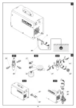
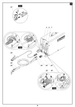
Connection to the grounding loop (see fig. 1)
Using grounding bolt
2
connect one grounding wire
clamp
29
to the machine (see fig. 1). Connect the sec
-
ond grounding wire clamp
29
to the working grounding
loop�
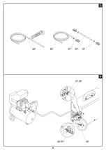
Compressor connection (see fig. 2-4)
•
Extract plugs
30
(see fig. 2.1).
•
Wind teflon tape (for tightening) around threaded
ends of connection pipes
31
and the threaded end of
manometer
32
(see fig. 2.2).
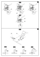
•
Screw connection pipes
31
and manometer
32
in
the pressure reducting valve body
26
and tighten them
with a wrench (see fig. 2.3).
•
Using screws
34
, fix bracket
33
as shown in fig. 2.4.
•
Unscrew the mounting nut
35
, install pressure re-
ducting valve
26
and tighten mounting nut
35
(see
fig. 2.5).
•
Cut hose piece
28
to the length necessary for con-
necting the outlet connecting pipe
31
("OUT" marking)
of pressure reducting valve
26
with connecting pipe
4
�
The second piece of hose
28
will be connected to the
compressor and inlet connecting pipe
31
("IN" mark-
ing) of pressure reducting valve
26
(see fig. 3-4). Put
clamps
27
on where hose
28
ends�
•
Connect the hoses
28
as shown in fig. 4. Fix hose
28
ending on the connecting pipes with clamps
27
�
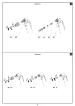
Cutting torch disassembly / assembly (see fig. 5-6)
[CT33131]
•
Unscrew protective cover
36
(see fig. 5).
•
Remove nozzle
38
, diffuser
39
and electrode
40
�
•
If the details are well worn or damaged, replace
them�
•
Assembly should be done in reverse sequence�
[CT33132]
•
Unscrew protective cover
36
(see fig. 6).
•
Unscrew nozzle
38
and electrode
40
from torch
body
37
�
•
If the details are well worn or damaged, replace
them�
•
Assembly should be done in reverse sequence�
Connecting / disconnecting cables (see fig. 7)
•
If necessary to connect connector to earth clamp ca-
ble
25
perform the operations, shown in fig. 7.1.
•
Open protective cover of socket
5
and attach earth
clamp
25
to the machine as shown in fig. 7.2.
•
Connect the cutting torch
24
to the machine (see
fig. 7.3):
•
connect a cutting torch control cable� Set a control
cable connector in socket
6
and tighten a nut
44
by
hand� During installation, pay attention that locating
tab inside of a socket fits a location slot of the cable
connector;
•
put the protective collar
23
on the screw nut
43
;
•
open protective cover of socket
7
;
•
put the screw nut
43
(by turning protective col-
lar
23
) on the connector thread
7
(see fig. 7.3), and
tighten it manually�
•
Disconnect of the cables in a reverse order�
Initial operating of the machine
Before starting the operation the following steps are
necessary:
•
always use the correct supply voltage: the power
supply voltage must match the information quoted
on the machine body;
Summary of Contents for CT33131
Page 1: ......
Page 3: ...3 ...
Page 4: ...4 ...
Page 5: ...5 ...
Page 6: ...6 ...
Page 7: ...7 ...
Page 8: ...8 ...
Page 9: ...9 ...
Page 49: ...49 ...
Page 50: ...50 ...
Page 51: ...51 ...
Page 52: ...52 ...
Page 53: ...53 ...
Page 54: ...54 ...
Page 55: ...55 ...
Page 56: ...56 ...
Page 57: ...57 ...
Page 58: ...58 ...
Page 59: ...59 ...
Page 60: ...60 ...
Page 61: ...61 ...
Page 62: ...62 ...
Page 63: ...63 ...
Page 64: ......