background image


3. Operation

13

English

3.1 Commissioning procedure

1.  Open  the  junction  box  of  the  detector  by  unscrewing  the  lid  in  an  anti-clockwise 

direction (having loosened the retaining grub-screw first).

2.  Check that all electrical connections have been made and are correct, as shown in 

Diagram 5.

3.  Measure the voltage across the ‘+’ and ‘-’ terminals and check a minimum supply of 

10 V d.c. is present.

4.  Leave the detector to stabilise for at least 45 minutes.
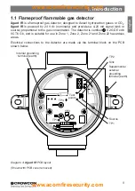
5.  Remove the PCB cover and check the amplifier balance by connecting a Digital Volt 

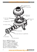
Meter (DVM) set to the dc mV range to test points TP3 and TP4 (see Diagram 4). 

Adjust potentiometer VR3 so that the DVM reads ‘0.00 mV’. The PCB cover can now 

be re-fitted.

6.  To zero the detector, connect the DVM to the test points marked ‘TP1’ and ‘TP2’ on 

the amplifier PCB, as shown in Diagram 4.

  Note: At the test points, Zero will read 40 mV = 4 mA. 
  Full scale deflection will read 200 mV = 20 mA. There is a current clamp of 25 mA 

on the 4-20 mA output.

Zeroing the detector

7. 

Hydrocarbon detectors: 

ensure the detector is in clean air. Adjust the ‘ZERO’ 

potentiometer (accessible via a hole in the PCB cover) until the DVM reads 40 mV. 

Check that the control panel display reads 0%LEL.

  Carbon Dioxide detectors: 

as air contains 300/400ppm of CO

2

 normally, the sen-

sor must be zeroed using 100% nitrogen test gas. 

Apply 100% N

2

 gas

 at a flow-rate 

of 0.5 litres per minute via a flow adaptor (part number C03005). Adjust the ‘ZERO’ 

potentiometer (accessible via a hole in the PCB cover) until the DVM reads 40 mV. 

Check that the control panel display reads 0%. Remove the zero gas.

Calibrating the detector

8.  Apply  calibration  gas  (concentration  should  ideally  be  at  least  50%  of  full  scale 

concentration) to the detector at a flow rate of 0.5–1 litre/minute via a flow adaptor 

(Part No. C03005)

. Contact Crowcon for the supply of calibration gas.

WARNING
Prior to carrying out any work ensure local regulations and site procedures are 

followed. Never attempt to open the detector or junction box when flammable 

gas is present. Ensure that the associated control panel is inhibited so as to 

prevent false alarms.

www.acornfiresecurity.com

www.acornfiresecurity.com

Summary of Contents for Xgard IR

Page 1: ...tie bedienings en onderhoudsinstructies Instrukcja monta u obs ugi i konserwacji Instru es de instala o opera o e manuten o M07692 Issue 6 April 2018 6 me dition Avril 2018 6 Ausgabe April 2018 Edici...

Page 2: ...www acornfiresecurity com www acornfiresecurity com...

Page 3: ...d IR Ansicht mit Ma en 2 Diagrama 2 Vista dimensionada de Xgard IR 2 Diagramma 2 Immagine dimensionata di Xgard IR 2 Afbeelding 2 Xgard IR maatschets 2 Rys 2 Wymiary Xgard IR 2 Diagrama 2 vista dimens...

Page 4: ...34 bersicht 36 1 Einleitung 37 2 Installation 38 3 Betrieb 41 4 Spezifikation 44 5 Ersatzteile und Zubeh r 45 Gew hrleistungserkl rung 46 Informaci n de seguridad 48 Introducci n 50 1 Introducci n 51...

Page 5: ...essoires 87 Garantieverklaring 88 Wskaz wki bezpiecze stwa 90 Informacje og lne 92 1 Wst p 93 2 Instalacja 94 3 Obs uga 97 4 Specyfikacja 100 5 Cz ci zamienne i akcesoria 101 Gwarancja 102 Informa es...

Page 6: ...www acornfiresecurity com www acornfiresecurity com...

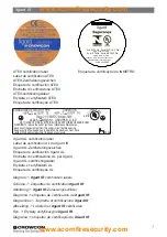
Page 7: ...ica o UL ATEX certification label Label de certification ATEX ATEX Zertifizierungszeichen Etiqueta de certificaci n ATEX Etichetta di certificazione ATEX ATEX certificeringslabel Etykieta z certyfikat...

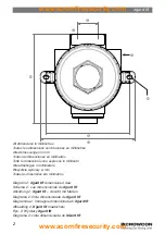
Page 8: ...lding 2 Xgard IR maatschets Rys 2 Wymiary Xgard IR Diagrama 2 vista dimensionada do XGard IR All dimensions in millimetres Toutes les dimensions sont donn es en millim tres Alle Abmessungen in mm Toda...

Page 9: ...25 1 2 3 4 NPT Ranuras para los acoples M6 1 4 155 5 Overall 146 CRS 166 3 Total Altura 111 Italiano Slot per viti M6 o 1 4 per il soffitto Slot CRS 36 Entrata cavi M20 M25 1 2 o 3 4 NPT Slot per viti...

Page 10: ...Lid O ring M04829 Diagram 3 Xgard IR exploded view Sch ma 3 Vue clat e du Xgard IR Abbildung 3 Xgard IR Vergr erte Ansicht Diagrama 3 vista despiezada de Xgard IR Diagramma 3 Disegno esploso di Xgard...

Page 11: ...Senser retainer O ring M04828 Sensor retainer PCB de sensor PCB amplificador Junta t rica de la cubierta M04829 Italiano Dove applicable i numeri di parte sono mostrati nella parentesi Coperchio O ri...

Page 12: ...ntre par nteses Etiqueta de certifica o Parafuso sem cabe a Prote o da pIaca M04770 Base do inv lucro Selo do sensor O ring de veda o do sensor M04828 Retentor do sensor M dulo do sensor PCI do amplif...

Page 13: ...IIC gases are likely to be present ref EN60079 14 2008 section 10 4 2 Hazardous area classifications Zone 0 An area classified as Zone 0 will have ignitable concentrations of flammable gases vapours o...

Page 14: ...e quote the model number gas range and sensor type when contacting Crowcon for advice or spares Product description Xgard IR comprises of a universal assembly to accommodate either HC or CO2 IR gas se...

Page 15: ...ation The detector is certified II 2 GD Ex db IIC T6 Gb and is suitable for use in Zone 1 Zone 2 Zone 21 and Zone 22 hazardous areas Electrical connections to the detector are made via the terminal bl...

Page 16: ...ed air currents Mount detectors in ventilation ducts if appropriate Consider the process conditions For example butane is normally heavier than air but if released from a process which is at an elevat...

Page 17: ...ropriate standards are met Xgard IR requires a dc supply of 10 30 V at up to 100 mA Ensure there is a minimum of 10 V at the detector taking into account the voltage drop due to cable resistance For e...

Page 18: ...om the sink position to the srce position as shown in Diagram 4 Note The internal grounding terminal see diagram 4 shall be used as the grounding means of the Xgard IR gas detector The external ground...

Page 19: ...the detector 7 Hydrocarbon detectors ensure the detector is in clean air Adjust the ZERO potentiometer accessible via a hole in the PCB cover until the DVM reads 40 mV Check that the control panel dis...

Page 20: ...liance with EN60079 20 1 where for example 100 LEL methane 4 4 volume UL certified detectors will be supplied calibrated for compliance with North American standards where 100 LEL methane 5 volume 3 2...

Page 21: ...n 2 Open the junction box of the detector by unscrewing the lid in an anti clockwise direction having loosened the retaining grub screw first 3 Unscrew the sensor retainer and remove the sensor and se...

Page 22: ...rature 20 C to 55 C 4 F to 131 F Humidity 0 95 RH non condensing Degree of protection IP65 Explosion protection Flameproof Approval code ATEX IECEx Inmetro II 2 GD Ex db IIC T6 Gb Extb IIIC T80 C Db T...

Page 23: ...nsor seal aluminium retainer M04885 Sensor retainer O ring M04828 Junction box lid O ring M04829 Amplifier PCB S011242 2 PCB cover M04770 Calibration adaptor C03005 Duct mounting kit S011918 Spare Sen...

Page 24: ...ed dismantled or tampered with The warranty does not cover misuse or abuse of the unit Any warranty on batteries may be rendered invalid if the use of an unauthorized charger is proven Non rechargeabl...

Page 25: ...guarantee and any extended warranty condition or statement express or implied statutory or otherwise as to the merchantable quality of our equipment or its fitness for any particular purpose is exclud...

Reviews: