12
English
2.4 Electrical connections
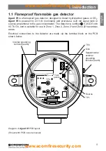
All connections are made via the screw terminal block mounted on the PCB in the
junction box. The terminals are marked ‘+’, ‘sig’ and ‘-’ and correct polarity should be
observed when connecting the detector to control equipment.
Xgard IR
is factory set
as a ‘current sink’ device unless otherwise specified when ordering. To reset to ‘current
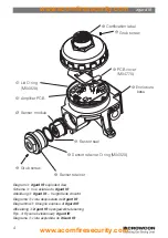
source’, open the junction box and move the two links on the amplifier PCB from the
‘sink position to the ‘srce’ position, as shown in Diagram 4.
Note:
The internal grounding terminal (see diagram 4) shall be used as the grounding
means of the
Xgard IR
gas detector. The external grounding terminal is only to be used
where local authorities permit or require such a connection. Where possible, to limit
radio frequency interference, the junction box and cable armour should be grounded at
the control panel (safe area) only to avoid earth loops.
Diagram 5:
Xgard IR
electrical connections
-VE
+VE
1
2
3
4
5
7
6
8
11
9
10
12
SIG
-VE
+VE
SIG
Xgard IR
PCB
Control panel
10-30 V cc
4-20 mA
(Sink or Source)
Earth


