Vortex FP Compact Installation & Operation Manual
8
Issue 1, January 2013
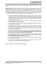
Vortex FP Compact requires cleaning as necessary to ensure the display window does not
become obscured. The enclosure, cables and glands should also be checked periodically to
ensure that Flameproof integrity is maintained.
For more detailed information on Vortex system maintenance, please refer to Section 7 of
the standard Vortex manual (part number M07211).
It may be necessary to open or remove the lid of the Vortex FP Compact enclosure in order
to perform some maintenance functions.
Vortex FP Compact must be completely de-
energised before the lid is opened; local procedures must be adhered to when
servicing equipment installed in a hazardous area.
3.4 V
ORTEX
FP C
OMPACT
D
ISPLAY AND
C
ONTROLS
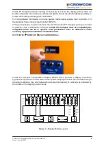
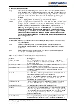
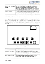
Vortex FP Compact incorporates a Display Module which provides a display of detector
signals and reports the current status of the system. Display functions are controlled using a
Crowmag calibration tool, which should be oriented (horizontally or vertically) as indicated by
the arrows on the display function fields.
%LEL
Power
%VOL
Channel
PPM
System
FIRE
Hold
Test
Fault
Channel
Reading
Alarm 2
Alarm 1
Fault
1
InhA
2
3
4
5
InhB
6
7
8
9
InhC
10
11
12
Step
Lamp
Test
Inhibit A
Inhibit C
Inhibit B
Figure 3 – Display Module Layout


