background image

9


Decrease 

LED 

backlight 

level 

CONTROL

+


Hold <CONTROL> 

and press < > 

repeatedly to 

decrease light 


Increase 

buzzer 

tone 

CONTROL

+

A


Hold <CONTROL> 

and press <A> 

repeatedly to 

increase buzzer 

tone 


Decrease 

buzzer 

tone 

CONTROL

+

B


Hold <CONTROL> 

and press <B > 

repeatedly to lower 

buzzer tone 


Note

If you started an operation incorrectly, press <

ENTER

>    to  exit and 

return to the previous mode. 

Operation 

How to Arm the System before Exit 


Preparing the System for Arming 

Verify that the green <Ready> indicator is lit.  This indicator is lit only when all zones are 

closed  (all  doors,  exits  and  windows  are  closed  and  motion  in  the  protected  area  is 

restricted  or  bypassed).    If  the  green  <Ready>  indicator  is  not  illuminated,  the  LCD 

displays the open zones and descriptions. 

Close open zones, or bypass them

. Bypass any zone you cannot close. For details see 

page 11. 

Note

: Bypassed zones are not protected. 


Arming the System 


When the system is ready, the LCD  display shows the system type, date and time, and 

the green <Ready> indicator is lit. 
Before leaving premises the system has to be armed. 
When the system is Ready, 

enter user code

 and then <

ENTER

> to arm the system. 


The system prompts you to exit the protected area. 


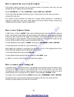
PowerWave  XX

TIME


DATE 

Areas Exiting 

A - 

Enter Code

****

www.msealarms.com.au

All manuals and user guides at all-guides.com

Summary of Contents for Power Wave CR16M

Page 1: ...v C N A Oct 2006 ELECTRONIC ENGINEERING LTD Power Wave CR16M LCD Keypad Users Operating and Programming Guide Version 2 00 www msealarms com au All manuals and user guides at all guides com a l l g u...

Page 2: ...t 9 How to Arm the System when Staying Home 10 How to Arm Partitions 11 How to Bypass Zones 11 How to use Chime If enable by Installer 12 Generate Threat or Duress 12 How to Read System Messages 13 Ho...

Page 3: ...ow to set Time and Date 17 How to operate the access control output 18 How to start Walk test Mode 18 How to Adjust Keypad Backlight Level 19 How to Adjust Buzzer Tone 20 PowerWave LCD Keypad Assignme...

Page 4: ...or and disarmed the garage from your cell phone so the white ware repairman can work on your washer The controller will support a 16 LED keypad or the more sophisticated LCD liquid Crystal Display key...

Page 5: ...nts to be displayed afterward on request to overview system activities and to analyze system performance for diagnostics The keyboard is illustrated in Figure 1 and the main components are detailed be...

Page 6: ...he LED indicators are listed in Table 2 Table 2 List of LED Indicators Design Function Bypass Indicates that there are bypassed zones Stay Indicates that the system is armed in STAY mode Armed Indicat...

Page 7: ...ds to arm relevant partition Only if enabled by installer Arm Stay STAY C O D E ENTER Initiates partial alarm when the user is home Only if enabled by installer Arm Stay STAY Initiates partial alarm w...

Page 8: ...trol for 2 seconds Change or Add Users code PROG M CODE ENTER Activates program mode to add or change Users codes For details see page 14 Customize keypad CONTROL ARM Enters Local Edit Program Mode Pr...

Page 9: ...l doors exits and windows are closed and motion in the protected area is restricted or bypassed If the green Ready indicator is not illuminated the LCD displays the open zones and descriptions Close o...

Page 10: ...System in Stay Mode This type of arming is used when people are present within the protected area At night time when the family is about to retire perimeter zones are protected but not the interior z...

Page 11: ...leave premises At the end of the procedure the ARMED indicator lights up to indicate that the system is armed and system message is displayed The indicators may go out after a few seconds depending o...

Page 12: ...ncy Alerts How to initiate Panic Press simultaneously CHIME and CONTROL for 2 seconds How to initiate Medical Alarm Press simultaneously CHIME and B for 2 seconds How to initiate Fire Alarm Press simu...

Page 13: ...re or abnormal events that may occur are indicated by trouble messages and the Trouble indicator is lit Press MEM to read out messages and other events stored in memory Trouble messages are listed in...

Page 14: ...ENT mode so you can add delete or change the user codes If you request it your installer can provide you with access to the INSTALLER mode as well To get into CLIENT mode provided the system is NOT ar...

Page 15: ...keyboard to enter your new Master code The code can hold any combination of 1 to 6 digits It is recommended using a multi digit code Press ENTER to save your new code To proceed to the next user code...

Page 16: ...for all of the addresses 1 8 998 999 you can also use the A button to return back to last saved text and you can use B button to return back to the default text Press ENTER to save textual descriptio...

Page 17: ...ENT mode To change the Time Date press In PW16 Press PROGRAM 823 ENTER 1 7 ENTER In PW4 8 Press PROGRAM 403 ENTER 1 7 ENTER In PW64 Press PROGRAM 678 ENTER 1 7 ENTER Where 1 7 the current day 1 Sun 2...

Page 18: ...are put into the memory buffer so they can be viewed at a later time To start Walk test mode while in CLIENT mode press PROGRAM 836 ENTER The keypad buzzer will beep at 1 second intervals Next trigge...

Page 19: ...How to Program Area Description While in Local Edit Program Mode Press PROG 998 and then ENTER You may edit any character one per each area To save changes press ENTER To update and transfer programm...

Page 20: ...increased to its maximum To decrease keyboard backlight hold CONTROL and press repeatedly until the light goes off How to Adjust Buzzer Tone The User can adjust the volume of the buzzer tone can be a...

Page 21: ...if the loss or damage is caused by Crow s own negligence or fault Crow does not represent that this product can not be compromised or circumvented that this product will prevent any person injury or p...

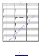
Page 22: ...ation Zone Zone Name 1 1 1 2 2 2 3 3 3 4 4 4 5 5 5 6 6 6 7 7 7 8 8 8 9 9 10 User Name Cont 10 11 31 11 12 32 12 13 33 13 14 34 14 15 35 15 16 36 16 17 37 18 38 19 39 20 40 21 41 22 42 23 43 24 44 25 4...

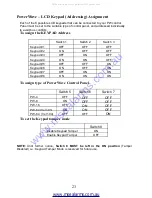
Page 23: ...notice Switch 8 MUST be left in the ON position Tamper Disabled i e Keypad Tamper Mode is reserved for future use Switch 1 Switch 2 Switch 3 Keypad 1 OFF OFF OFF Keypad 2 ON OFF OFF Keypad 3 OFF ON OF...

Page 24: ...24 www crowaust com au crow crowaust com au Oct 2006 www msealarms com au All manuals and user guides at all guides com...

Reviews: