2-4-5
U29PHSDA
A
(S-2)
[7]
(L-12)
[49]
[50]
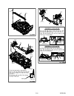
Fig. DM6H
View for A
Desolder
from bottom
Lead with
Red Stripe
[8]
[9]
(S-4)
(S-3)
LDG
Belt
View for A
Desolder
from bottom
Lead with White Stripe
A
[8]
Fig. DM7H
[11]
[13]
[12]
[10]
(L-4)
(P-3)
(P-2)
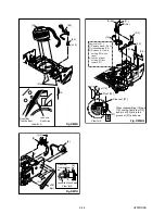
Fig. DM8H-1
Pin of [12]
Pin of [10]
Groove of [27]
View for A
When reassembling [10] and
[12], confirm that pin of [10]
and pin of [12] are in the
groove of [27] as shown.
[27]
Removal of [11]
1) Remove screw
(S-4A).
2) Unhook spring
(P-2).
3)
Release (L-4) while
holding [12] with a
finger.
4)
Loosen a finger
holding [12] and
remove [11].
A
(S-4A)
Summary of Contents for F5000M
Page 22: ...1 8 3 1 8 4 HG232SCM1 Main 1 5 Schematic Diagram...
Page 23: ...Main 2 5 Sensor Schematic Diagrams 1 8 5 1 8 6 HG232SCM2...
Page 24: ...Main 3 5 Schematic Diagram 1 8 7 1 8 8 HG232SCM3...
Page 25: ...Main 4 5 Jack Schematic Diagrams 1 8 9 1 8 10 HG232SCM4...
Page 29: ...1 8 17 1 8 18 Jack CBA Top View Jack CBA Bottom View BHG470F01014C...
Page 35: ...1 13 1 HG232FEX EXPLODED VIEWS Front Panel A1X...
Page 69: ...F5000M HG232ED 2004 04 22...


