


2-3-1
U29P2HSMA
MECHANICAL ALIGNMENT PROCEDURES
Explanation of alignment for the tape to correctly run
starts on the next page. Refer to the information below
on this page if a tape gets stuck, for example, in the
mechanism due to some electrical trouble of the unit.
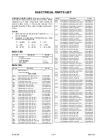
Service Information
A. Method for Manual Tape Loading/Unloading
To load a cassette tape manually:
1. Disconnect the AC plug.
2. Remove the Top Case and Front Assembly.
3. Insert a cassette tape. Though the tape will not be
automatically loaded, make sure that the cassette
tape is all the way in at the inlet of the Cassette
Holder. To confirm this, lightly push the cassette
tape further in and see if the tape comes back out,
by a spring motion, just as much as you have
pushed in.
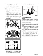
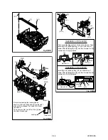
4. Turn the LDG Belt in the appropriate direction
shown in Fig. M1 for a minute or two to complete
this task.
To unload a cassette tape manually:
1. Disconnect the AC plug.
2. Remove the Top Case and Front Assembly.
3. Make sure that the Moving guide preparations are
in the Eject Position.
4. Turn the LDG Belt in the appropriate direction
shown in Fig. M1 until the Moving guide prepara-
tions come to the Eject Position. Stop turning when
the preparations begin clicking or can not be
moved further. However, the tape will be left wound
around the cylinder.
5. Turn the LDG Belt in the appropriate direction con-
tinuously, and the cassette tape will be ejected.
Allow a minute or two to complete this task.
B. Method to place the Cassette Holder in the tape-
loaded position without a cassette tape
1. Disconnect the AC Plug.
2. Remove the Top Case and Front Assembly.
3. Turn the LDG Belt in the appropriate direction
shown in Fig. M1. Release the locking tabs shown
in Fig. M1 and continue turning the LDG Belt until
the Cassette Holder comes to the tape-loaded
position. Allow a minute or two to complete this
task.
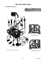
Moving guide T preparation
(Eject Position)
LDG Belt
Push the locking tab gently to unlock
when loading without a cassette.
Side View
Moving guide S preparation
(Eject Position)
Push the tape
to load it.
UNLOAD
/EJECT
LOAD
Fig. M1
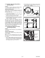
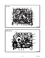
Top View
Fig. M2
Bottom View
Cam Gear
LDG Belt (B)
UNLOAD
/EJECT
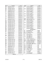
Summary of Contents for F5000M
Page 22: ...1 8 3 1 8 4 HG232SCM1 Main 1 5 Schematic Diagram...
Page 23: ...Main 2 5 Sensor Schematic Diagrams 1 8 5 1 8 6 HG232SCM2...
Page 24: ...Main 3 5 Schematic Diagram 1 8 7 1 8 8 HG232SCM3...
Page 25: ...Main 4 5 Jack Schematic Diagrams 1 8 9 1 8 10 HG232SCM4...
Page 29: ...1 8 17 1 8 18 Jack CBA Top View Jack CBA Bottom View BHG470F01014C...
Page 35: ...1 13 1 HG232FEX EXPLODED VIEWS Front Panel A1X...
Page 69: ...F5000M HG232ED 2004 04 22...


