AHRS500GA Series Operator’s Manual
Doc# 7430-0060-02 Rev. A
Page 21
2. Connect the other 15 pin end of the calibration cable to the aircraft
cable.
3. Connect the 9-pin end of the cable to the serial port of your
computer.
4. The calibration switch on the cable should be set to OFF.
Powering up the unit with the switch in the ON position will erase
the magnetometer calibration.
5. With the AHRS500GA connected to yo ur PC serial port and
powered, open the GyroView software.
6. GyroView should automatically detect the AHRS500GA and
display the serial number and firmware version if it is connected.
7. If GyroView does not connect, check that you have the correct
COM port selected. You find this under the “DMU” menu.
8. If the status indicator says, “Connected”, you’re ready to go. If the
status indicator doesn’t say connected, check the connections
between the AHRS500GA and the computer; check the power;
check the serial COM port assignment on your computer.
9.
Let the AHRS500GA warm up for 60 seconds when first turned
on. This allows the Kalman filter to estimate the rate sensor
biases. Now you’re ready to calibrate the AHRS500GA.
9.4
Calibration Process
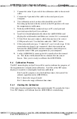
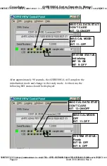
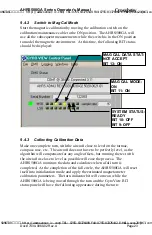
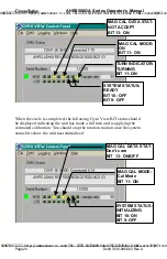
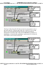
The BIT status display in GyroView will be used to indicate the progress of
the magnetometer compensation calibration. Four bits of the BIT status
display are used for evaluating the hard iron calibration:
Bits 9 and 10 comprise a two -bit field that shows the state of the
attitude algorithm in the AHRS500GA
Bit 11 shows the mag cal mode
Bit 13 shows the mag calibration data status
9.4.1
Starting the Calibration
If the power has been applied less than approximately 90 seconds, the Gyro
View BIT display will indicate that the AHRS500GA is initializing:
SUNSTAR传感与控制 http://www.sensor-ic.com/ TEL:0755-83376549 FAX:0755-83376182 E-MAIL:[email protected]
SUNSTAR自动化 http://www.sensor-ic.com/ TEL: 0755-83376489 FAX:0755-83376182 E-MAIL:[email protected]

