


AHRS500GA Series Operator’s Manual
Doc# 7430-0060-02 Rev. A
Page 5
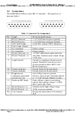
3.2.1
I/O Cable
The user must provide a shielded cable with the shield connected to the I/O
connector shell in order to provide the required EMI protection. The cable
sent with the unit is intended to provide the user with the ability to perform
a magnetometer calibration, and provide routine magnetometer calibration
maintenance of the system, and will not provide adequate shielding.
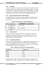
3.2.2
Power Input and Power Input Ground
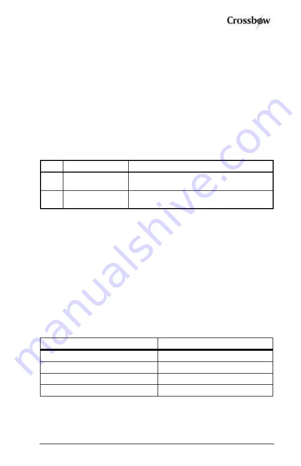
The AHRS500GA power requirements are described in the table below. It
is designed to operate with either a nominal 14VDC or 28VDC aircraft
power system.
Table 2 Electrical Power Input Requirements
Item
Requirement
AHRS500GA specification
1. Input Supply
voltage
10-40 VDC
2. Input Supply
Current
1 Amp (max)
3.2.3
Case Ground
The case is electrically connected to the I/O connector shell. The shell
should be electrically connected to the user’s cable shield. The case is
isolated from the Power Input Ground, and should be bolted to a good
conducting surface that is grounded.
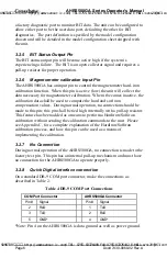
3.2.4
Serial Data Interface
The interface specification is a factory configurable RS-422 or RS-232, also
with factory configurable baud rates (see table below) depending on the
model configuration chosen. Data output is continuous at a fixed frequency
dependant on the baud rate (see table below).
Table 3 Supported BAUD Rates and Output Rates
BAUD Rate
Output Rate
9600
25
19200
50
38400
100
57600
200
The unit has both an RS-232 and RS422 serial interface. During factory
configuration, one port is configured as the user data port while the other is
SUNSTAR传感与控制 http://www.sensor-ic.com/ TEL:0755-83376549 FAX:0755-83376182 E-MAIL:[email protected]
SUNSTAR自动化 http://www.sensor-ic.com/ TEL: 0755-83376489 FAX:0755-83376182 E-MAIL:[email protected]


