2099-42 CLOCK GENERATOR
C
ROSS
T
ECHNOLOGIES, INC.
EXT. AUTO INT.
INT FREQ.
INT/
EXT
MAN
PLL
ALM
REF
ALM
MODE
MONITOR
J1 - Buffered
output monitor of
the 12.288 MHz
internal VCXO
S1 - EXT. / AUTO / INT.- Manually forces output clock frequency
to be locked to EXTERNAL reference or controlled by
INTERNAL VCXO. In AUTO the output clock frequency is locked
to the external reference unless it is remove when automatic
switchover to the internal VCXO occurs.
DS2 - EXTERNAL /
INTERNAL REF LED
- Lights GREEN if 10
MHz external
reference controls
output clock
frequency, RED if the
internal VCXO alone
does.
DS1 - MANUAL
LED - Lights RED
when S1 is not in
AUTO.
DS4 - PLL ALARM LED -
Lights RED when 10 MHz
external reference is removed
(<0.2 Vp-p) or VCXO is
defective. If S1 is in
INTERNAL REF and 10 MHz
reference is present, DS4 will
light occasionally depending
on how far off in frequency the
VCXO is set from locking to it.
DS3 - EXTERNAL
REFERENCE
PRESENT LED -
Lights GREEN when
10 MHz external
reference is present
and RED if below 0.4
Vp-p
R20 - INTERNAL
REFERENCE
FREQUENCY
ADJUSTMENT Ten
turn potentiometer that
adjusts the internal
VCXO to 12.288000
MHz when in the
INTERNAL
REFERENCE mode.
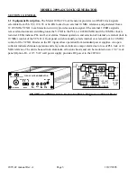
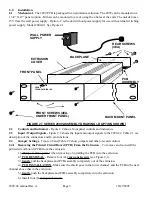
FIGURE 2.2 2099-42 Front Panel Controls and Indicators
FIGURE 2.3 2099 Inputs and Outputs
J2
J4 - I/O BARRIER STRIP - Provides connections for
audio, data, alarm signals, etc. Pin numbers are as
shown upside down on the connector. See Table 2.1
J2 - DC IN - The
+15 VDC AND -15
VDC regulated DC
voltage from the
wall power supply
-15 +15
GND
J1 - BNC IN/OUT - Signal from pin 2 or 3 (as
set by strap beside J1) of PCB which is for
subcarrier, video, IF and RF signals.
JP1 - J1 OUTPUT TERMINATION
TERM = 75
TERMINATION
2 - 3 = NO 75
TERMINATION
> 2K impedance
1 2 3
JP1
TERM
J4
1 2 3 4 5 6 7 8 9 10 11 12 13 14 15 16 17 18
2099-42 manual Rev. A
Page 7
10/27/2005

