


Crestron
TPS-1700
Isys
®
Wired 5.7 Inch Tabletop Touchpanel
Operations Guide - DOC. 6223A
Isys
®
Wired 5.7 Inch Tabletop Touchpanel: TPS-1700
•
7
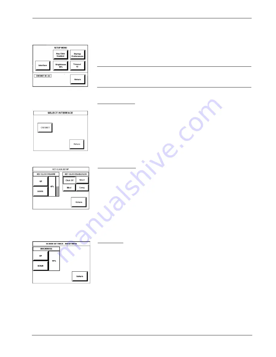
Setup Menu
SETUP MENU
To obtain the SETUP MENU, shown to the left, press the
Setup
button from the
MAIN MENU. The SETUP MENU offers a series of buttons, which open additional
menus and screens that are detailed in subsequent paragraphs. After setup parameters
have been set, select the
Return
button to return to the MAIN MENU.
NOTE:
For convenience, the current CRESNET ID setting is displayed in the lower
left corner.
NOTE:
All touchpanel settings are automatically saved in non-volatile memory.
Select Interface
SELECT INTERFACE
The touchpanel communicates with a control system to activate commands or to
display feedback from components within the system. The communication interface
must be correctly specified or communication will not occur. To set communication
parameters, first select the
Interface
button on the SETUP MENU to display the
SELECT INTERFACE screen, shown to the left. Then, select the
CRESNET
button
to display the CRESNET INTERFACE MENU. Use that screen to set the Cresnet
network identity (CRESNET ID).
After the Cresnet ID setting has been verified, touch the
Return
button at the bottom
of the screen to save the setting and display the SELECT INTERFACE menu.
KEY CLICK SETUP
Key Click Setup
From the SETUP MENU, press the
Key Click Enabled
button to open KEY CLICK
SETUP screen. (If the function is currently disabled, the button legend is “
Key Click
Disabled
.”) To enable an audible tone (beep) when the touchpanel buttons are
pressed, select among the
Short, Med,
or
Long
KEY CLICK ENABLE/LEN
buttons to set the duration of the tone. The touchpanel responds with a corresponding
signal. To disable the feature, select
Click Off
.
Use the KEY CLICK VOLUME
UP
and
DOWN
buttons to increase and decrease
the volume of the signal. The area to the right of the buttons shows the relative
volume from 0% to 100%, both as a numeric value and, for a quick visual reference,
as an analog bar.
Select the
Return
button to return to the SETUP MENU.
SCREEN SETTINGS -
BRIGHTNESS
Brightness
From the SETUP MENU, press the
Brightness
button to open the SCREEN
SETTINGS – BRIGHTNESS screen. The
UP
and
DOWN
buttons increase and
decrease screen brightness, respectively. The area to the right of the buttons shows
the relative brightness from 0% to 100%.
Select the
Return
button to return to the SETUP MENU.


