background image

34 • HD-PS401 and HD-PS402

Web Interface Configuration Guide — Doc. 9196B

l

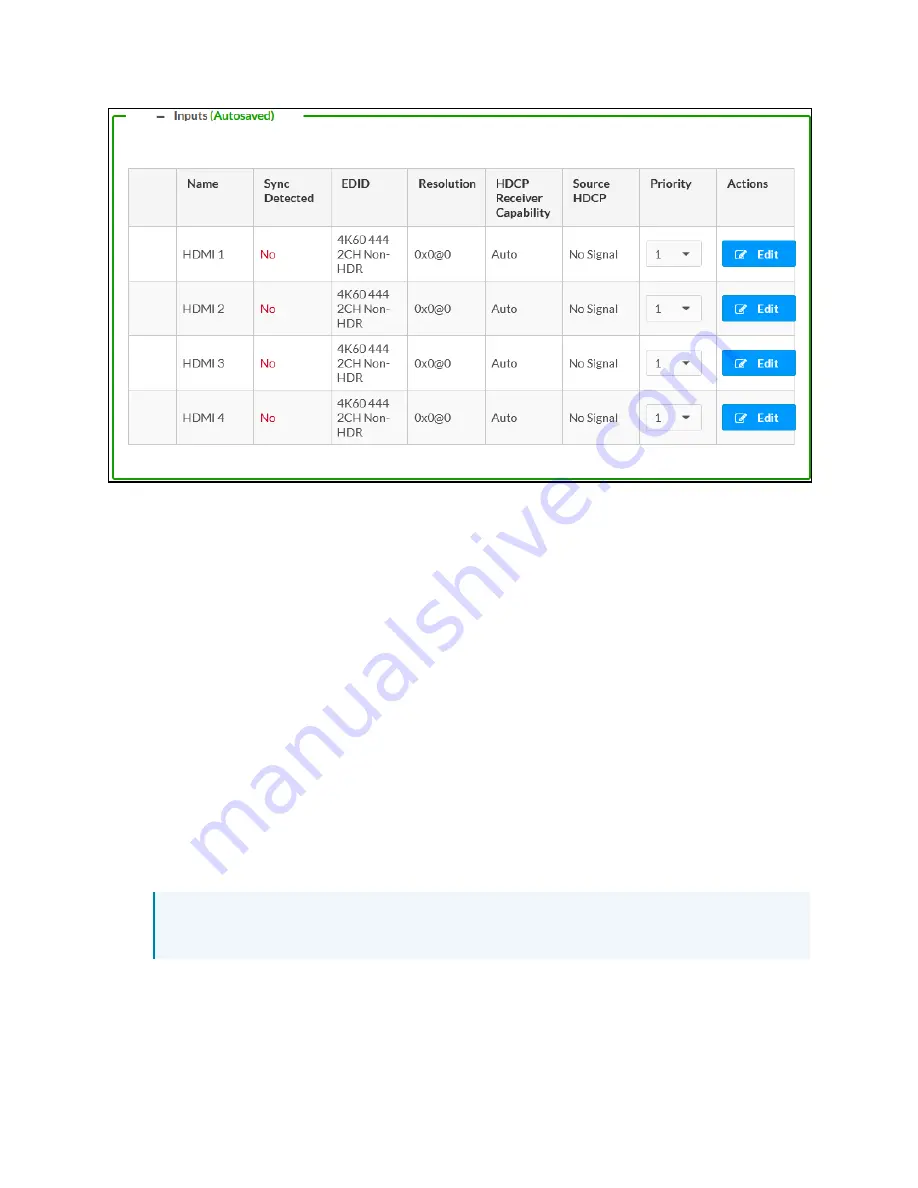
Name: Displays the name of the input. To modify the name of the input, click Edit under
the Actions column and enter the new name in this field.

l

Sync Detected: Indicates whether a valid video signal is detected at the corresponding
input.

l

EDID: Displays the selected predefined EDID file. To modify the existing setting, click Edit
under the Actions column and select an EDID from the EDID drop-down menu.

l

Resolution: The resolution when video is detected. If no video is detected, the reported
resolution will be 0x0@0.

l

HDCP Receiver Capability: Specifies whether HDCP support for this input will be Disabled,
Auto, HDCP 1.4 or HDCP 2.x. To modify the existing setting, click Edit and select the
desired option from the HDCP Receiver Capability drop-down menu.

l

Source HDCP: Reports HDCP 1.x or HDCP 2.x when the HDCP source is connected. Reports
Non-HDCP when a non-HDCP source is connected and reports No Signal when no source
is connected.

l

Priority: Use the drop-down list to set the priority.

The lowest number has the highest priority. For example, priority 1 has a higher priority
than priority 4. By default, all of the inputs are set to priority 1.

NOTE: When the priority is set with the same value for other inputs, then it switches
to the latest connected input.

Edit an Input Port

Edit the input port by clicking the Edit button on the row. The following options appear:

Summary of Contents for HD-PS402

Page 1: ...HD PS401 and HD PS402 4x1 and 4x2 4K60 4 4 4 HDR Presentation System Web Interface Configuration Guide Crestron Electronics Inc ...

Page 2: ...e Crestron the Crestron logo DM Lite DMPS Lite and XiO Cloud are either trademarks or registered trademarks of Crestron Electronics Inc in the United States and or other countries HDMI and the HDMI logo are either trademarks or registered trademarks of HDMI Licensing LLC in the United States and or other countries Active Directory is either a trademark or registered trademark of Microsoft Corporat...

Page 3: ...n System 9 Restoring to Factory Default Settings 9 Updating Firmware 10 Downloading Logs 10 Managing Certificates 11 To Add Certificates 12 To Delete Certificates 12 Managing EDIDs 13 To Load a Custom EDID File 14 To Delete a Custom EDID File 15 Downloading Configuration 15 Uploading Configuration 16 Status 17 Device 18 Occupancy Sensor 20 Input Output 20 Inputs 21 Outputs 21 Network 22 Control Sy...

Page 4: ...Individual DM Lite or HDMI Output Settings 48 Routing 52 Security 54 Current User 54 Users 55 Create a New Local User 56 Add an Active Directory User 56 Delete a User 57 View User Details 57 Update User Details 58 Groups 59 Create a Local Group 60 Add an Active Directory Group 60 Delete a Group 61 View Group Details 61 802 1x Configuration 62 To Configure Presentation System for 802 1X Authenticat...

Page 5: ...resentation System allows you to view status information and configure network and device settings Access the Web Interface The web interface is accessed from a web browser The following table lists operating systems and their corresponding supported web browsers OPERATING SYSTEM SUPPORTED WEB BROWSERS Windows operating system Chrome web browser version 31 and later Firefox web browser version 31 ...

Page 6: ...P address of the AV switcher into a web browser NOTE To obtain the IP address press the Setup button on the AV switcher to display the IP address on the HDMI output The IP address is displayed for 20 seconds 2 If you are creating a user account for the first time do the following otherwise skip to step 3 a Enter a username in the Username field b Enter a password in the Password field c Re enter t...

Page 7: ...access the web interface by opening a web browser within the Crestron Toolbox application do the following 1 Open the Crestron Toolbox application 2 From the Tools menu select Device Discovery Tool You can also access the Device Discovery Tool by clicking the Device Discovery Tool button in the Crestron Toolbox toolbar The Presentation System are discovered and listed in the device list on the lef...

Page 8: ... Discovery Tool can be used 3 Double click your device in the Device Discovery Tool list 4 Enter your credentials in the Authentication Required dialog and click Log In 5 Click the Web Configuration button in the Configuration page displayed on the left side of the Device Discovery Tool Sign Out from the Web Interface The web interface provides you the option to sign out of the session Click the u...

Page 9: ...s are mentioned in the product page Here are the links Crestron Presentation Systems Product Specification Sheet l HD PS401 l HD PS402 l https www crestron com Products Video DigitalMedia Switchers Fixed Switchers HD PS401 l https www crestron com Products Video DigitalMedia Switchers Fixed Switchers HD PS402 ...

Page 10: ... 9196B Installation To install the Crestron HD PS401 and HD PS402 follow the link to the Quick Start guide for instructions Crestron Presentation Systems Quick Start Guide l HD PS401 l HD PS402 l https www crestron com docs 9067 l https www crestron com docs 8991 ...

Page 11: ...401 and HD PS402 7 Configuration You can set up your Crestron HD PS401 and HD PS402 as mentioned in the following topics 1 Actions Menu on the next page 2 Status on page 17 3 Settings on page 24 4 Security on page 54 5 802 1x Configuration on page 62 ...

Page 12: ... top right side of the interface and provides quick access to common device functionality of the Presentation System such as l Reboot l Restore l Update Firmware l Download Logs l Manage Certificates l Manage EDIDs l Download Configuration l Upload Configuration l Manage Images l Manage Occupancy Sensor l Save Changes l Revert ...

Page 13: ...onnect to the device Restoring to Factory Default Settings 1 Click Restore in the Actions drop down menu to restore the settings of the Presentation System to factory defaults NOTE When settings are restored all settings including the network settings will revert to the factory default If a static IP address is set restoring the device to factory default settings will revert the IP address to the ...

Page 14: ...sired firmware file and then click Open The selected firmware file name is displayed in the Firmware Upgrade dialog 4 Click Load and wait for the progress bar to complete and for the OK button in the message to become clickable 5 Click OK The device with new firmware can now be accessed Downloading Logs Click Download Logs in the Actions drop down menu The log file is downloaded to the Downloads f...

Page 15: ...to the device Root certificates must be self signed l Intermediate The Intermediate storage holds non self signed certificates that are used to validate the authentication server These certificates will be provided by the network administrator if the network does not use self signed Root certificates l Machine The machine certificate is an encrypted PFX file that is used by the authentication serv...

Page 16: ...a Machine Certificate enter the password provided by the network administrator 5 Click OK This will add the certificate to the list box displaying the file name and expiration date The certificate is now available for selection and can be loaded to the device To Delete Certificates 1 Click the corresponding certificate tab 2 Click the trashcan button in the Actions column to delete the certificate...

Page 17: ...IDs are displayed in the Default EDIDs tab of the EDID Management dialog The following EDIDs are available l 01 DM default l Consumer 1080p60 HBR l Consumer 720p60 HBR l Laptop 16x9 1080p60 2ch l Laptop 16x10 1920x1200 2ch l Laptop 16x10 1280x800 2ch l Laptop widescreen 2ch l Consumer 1080p50 HBR l Consumer 720p50 HBR l Laptop 16x9 1080p50 2ch l DM Default 4k 30Hz 2ch l DM Default VGA EDID l DM De...

Page 18: ...R HDR10 To Load a Custom EDID File 1 In the EDID Management dialog click the User EDIDs tab and then click the Add EDID button 2 Click the Browse button in the File Upload dialog 3 Navigate to the desired custom EDID file cedid extension select the file and then click Open 4 Click Send EDID A prompt appears asking for confirmation that the EDID file be uploaded to the device 5 Click OK ...

Page 19: ...om EDID File NOTE Only custom EDID files that are not applied to an input can be deleted Built in EDID files cannot be deleted 1 Click the User EDIDs tab and then click the trashcan button in the row of the custom EDID files to be deleted 2 Click Yes in the Confirmation dialog to confirm the deletion Click No to cancel After a successful deletion the custom EDID file is removed from the Send EDID ...

Page 20: ...on 1 Click Upload Configuration in the Actions drop down menu 2 Click the Browse button 3 Navigate to the configuration file select the file and then click Open 4 Click the Load button The Confirmation dialog appears 5 Click Yes Reboot Now to reboot the device The Reboot message box appears ...

Page 21: ... the Presentation System such as Model Name Serial Number and Firmware Version current network settings such as Host Name and IP Address etc input and output ports as well as information about the connection to the control system The Status tab can be accessed at any time by clicking the Status tab of the Presentation System interface Information displayed on the Status tab is organized into diffe...

Page 22: ... Interface Configuration Guide Doc 9196B Device The Device section displays the Model Serial Number and Firmware Version of the Presentation System Click More Details to review additional information about the Presentation System ...

Page 23: ...Web Interface Configuration Guide Doc 9196B HD PS401 and HD PS402 19 ...

Page 24: ...pancy Sensor The Occupancy Sensor section lists all the sensors added to the Presentation System Input Output The Input Output section displays information about available inputs and outputs of the Presentation System NOTE Output HDMI2 DMLITE2 is not applicable for HD PS401 ...

Page 25: ...is connected Outputs l Name Displays the name of the output source l Sink Connected Displays Yes if connection is detected or No if connection is not detected l Resolution o Displays the detected resolution when a video signal is being transmitted In the event an HDMI cable is connected to the display downstream device but the device is turned off the last detected resolution will be displayed unt...

Page 26: ...and DNS Servers NOTE By default the host name of the Presentation System consists of the model name followed by the MAC address of the device For example HD PS402 00107FE12B63 Additionally the following IPv4 addressing information is provided l Host Name l Domain Name l Primary Static DNS l Secondary Static DNS l DHCP Enabled l IP Address l Subnet Mask l Default Gateway l Link Active l MAC Address...

Page 27: ...ntrol System section displays connection information consisting of the following l Encrypt Connection ON or OFF l IPID Reports the currently used IP ID of the Presentation System l IP Address Hostname IP address of the control system l Room ID Displays the room ID l Status OFFLINE or ONLINE ...

Page 28: ...nual Save Click the Save Changes button in the Actions menu to save manually l Autosaved This feature is available only for some settings Once a setting is modified the changes are automatically saved The autosave status is indicated next to the section title as follows Information displayed on the Settings tab is organized into different sections System Setup The System Setup section displays inf...

Page 29: ...omain Primary Static DNS and Secondary Static DNS NOTE By default the host name of the Presentation System consists of the model name followed by the MAC address of the device For example HD PS622 00107FF40115 The host name that is entered here is also displayed on the top left page of the portal Adapter 1 Displays DHCP IP Address Subnet Mask and Default Gateway of the Presentation System ...

Page 30: ...isabled When DHCP is disabled manually enter information in the following fields o Primary Static DNS Enter a primary DNS IP address o Secondary Static DNS Enter a secondary DNS IP address o IP Address Enter a unique IP address for the Presentation System o Subnet Mask Enter the subnet mask that is set on the network o Default Gateway Enter the IP address that is to be used as the network s gatewa...

Page 31: ... accidental changes to the device settings By default the front panel is unlocked allowing the front panel buttons to function l Front Panel LEDs To enable the front panel LEDs move the Front Panel LEDs slider to the right position To disable the front panel LEDs move the slider to the left position Cloud Settings The Cloud Settings section provides functionality to enable or disable the XiO Cloud...

Page 32: ...e the default URL to download the updates from the Crestron server b Use a custom URL To enable a custom URL move the Custom URL slider to the right position In the Custom URL Path text box enter the path to the manifest file in the FTP or SFTP URL format 4 Set a schedule for the automatic firmware update by doing either of the following a Select the desired Day of Week and Time of Day 24 hour for...

Page 33: ...ach sever the following configuration inputs are required l IP address or DNS name of NTP server l Network port of NTP server default to 123 l Authentication method None MD5 or SHA1 Default is None l If authentication is set to MD5 or SHA1 an authentication key must be entered 3 Click Synchronize Now to perform time synchronization between the device s internal clock and the time server Time Confi...

Page 34: ...l System Save message box appears indicating that the control system settings were saved successfully Click the Revert button to revert to the previous settings without saving Service Ports The USB port available on the front panel of the Presentation System can be enabled or disabled using the USB Service Port By default the USB Service Port is disabled l l USB Service Port To enable the USB Serv...

Page 35: ...y saved device configuration file l Load the device firmware using the file name to upgrade l Factory restore NOTE Device shall create result txt file after executing the command in the USB root directory To upgrade the firmware and download the logs 1 Enable the USB Service Port and plug in the USB device with the firmware file 2 Press and hold the Setup button for 10 seconds to load the device f...

Page 36: ...ection on individual inputs Global Settings Enable or disable the Priority Routing for local inputs HDCP inputs that are in the Presentation System and transmitter inputs Priority Routing works only if Auto Routing is enabled When Auto Routing is disabled you cannot modify any settings related to the priority routing For more information on Auto Routing see the Routing topic Global EDID In the Sen...

Page 37: ...50 2ch l DM Default 4k 30Hz 2ch l DM Default 4k 60Hz 2ch l DM Default 4k 60Hz HBR l 4K60 444 2CH Non HDR l 4K60 444 2CH HDR l 4K60 444 2CH HBR HDR l 4K60 444 2CH HDR DCI l 4K60 444 HBR Non HDR l 4K60 444 2CH HDR10 l 4K60 444 HBR HDR10 The selected EDID is automatically sent to all inputs and appears in the EDID drop down menu in the Inputs section of the page NOTE Copy output DMLITE2 and Copy outp...

Page 38: ...cifies whether HDCP support for this input will be Disabled Auto HDCP 1 4 or HDCP 2 x To modify the existing setting click Edit and select the desired option from the HDCP Receiver Capability drop down menu l Source HDCP Reports HDCP 1 x or HDCP 2 x when the HDCP source is connected Reports Non HDCP when a non HDCP source is connected and reports No Signal when no source is connected l Priority Us...

Page 39: ...HDCP encrypted content Select a value from the drop down list o Auto By default auto is selected The source content is streamed to the output o Disable Allows only non HDCP content o HDCP 1 4 Allows 1 4 and non HDCP content o HDCP 2 x Allows 1 4 2 x and non HDCP content EDID Select an EDID from the drop down list This is used to set the EDID to the input port ...

Page 40: ...DCP 2 x when an HDCP source is connected o Reports Non HDCP when a non HDCP source is connected o Reports No Signal when no source is connected More Details l Source Content Stream Type 0 or 1 l HDCP State Shows the current state of the input l Interlaced o Interlaced Input signal Yes o Progressive Input signal No l Horizontal Resolution Reports the input signal horizontal resolution Valid values ...

Page 41: ... the number of audio channels detected for the input signal Valid range is 0 to 8 When no audio is detected it displays as 0 l Audio Channels Reports the audio format for the input signal Valid formats are o No Audio o PCM o LBR Compressed o HBR Compressed Inputs l Name Displays the name of the input source NOTE The rest of the table properties are described in the Input Settings and More Details ...

Page 42: ...e Mic or Line signal level has exceeded 50 of the maximum level supported by the hardware or 2 dB below the input clip level l Mic Line Mode Used to set the mode of the input Applicable only for Mic Line input 1 and 2 l Phantom Power If enabled it delivers the power to the Phantom Mic By default it is disabled l Mute Used to mute a Mic or Line input Outputs The Outputs section can be used to confi...

Page 43: ...s column and then enter the new name in this field l Sink Connected Yes is displayed when connection is detected or No is displayed when no connection is detected For AUX outputs this will be N A l Resolution The resolution when video is detected If no video is detected the reported resolution will be 0x0 0 For AUX outputs this will be N A l HDCP Transmitter Mode Displays the selected HDCP Transmi...

Page 44: ...0 to 20 dB The default value for all Gain is 0 dB Gain has two controls slider and text entry field l Mute Used to mute the individual listed ports l Volume Used for overall output gain The Volume slider has a valid range of 80 to 20 dB The default value for all volumes is 0 dB Output Volume has two controls slider and text entry field l Stereo Used to enable stereo at the AUX output l Mute Used t...

Page 45: ...6B HD PS401 and HD PS402 41 Edit HDMI DMLITE Output Settings 1 Click the Edit button in the Actions column to edit the HDMI settings of the selected HDMI output 2 In the Edit Output dialog under the Output Settings section update the following ...

Page 46: ...n enabled to blank the HDMI output signal video The output continues to pass the audio signal while the video signal does not get displayed l Select the Resolution from the drop down list to upscale or downscale the video The following resolutions are listed o Auto HDMI o Auto DM LITE default o 720p50 o 720p60 o 1080i 25Hz o 1080i 30Hz o 1080p 24Hz o 1080p 25Hz o 1080p 30Hz o 1080p 50Hz o 1080p 60...

Page 47: ... resolution is 1080p and the input resolution is 640 x 480 this will result in a 640 x 480 display in the middle of the screen with a black bar surrounding it o Zoom Image is zoomed in to fill the screen maintaining the aspect ratio and eliminating black bars but a portion of the image may be lost l Set the Underscan value of the device used to fit to a display Range is 0 10 in 0 1 steps b Under t...

Page 48: ...r 2 dB below the input clip level n Volume Used for overall output gain The Volume slider has a valid range of 80 20 dB The default value for all volumes is 0 dB Output Volume has two controls slider and text entry field n Stereo Used to enable stereo at the AUX output n Delay Used to delay in ms the audio played at the AUX output Delay has two controls slider and text entry field n Mute Used to m...

Page 49: ...not routed to an output this image is displayed in the output l Time to wait after no video is detected Set the time to wait until no video is detected at the output If the video is not detected then the background image is displayed o The minimum time is 5 seconds o The maximum time is 65 535 seconds o The default time is 5 seconds l Aspect Ratio Always display actual 1 1 image size ...

Page 50: ...ge appears in the preview section NOTE When the image is uploaded and processed the status of the image appears as Error State Pending State Processing State or Ready State o From Remote Server Enter the image URL in the Remote Path field l Preview Previews the selected image You can see the status of the image during the time of upload by hovering the cursor over the image preview area l Refresh ...

Page 51: ...lider d Under the Text Overlay section enter the following l Text Overlay Move the Text Overlay slider to enabled right or disable left By default the text overlay feature is disabled l Text to Display Type text to display over the video l Background Transparency Move the Background Transparency slider or enter a value to adjust the background transparency The exact transparency value ranging from...

Page 52: ...eo outputs To enable the audio and video outputs move the slider to the left b Edit the name of the HDMI output in the Name field optional c Select the desired option from the HDCP Transmitter Mode drop down menu to set the HDCP Mode as follows l Auto Allows all the content to be transmitted l Follow Input Authenticates each time the input sync changes its state The output will authenticate to the...

Page 53: ... name l Name Displays the connected display manufacturer name l Serial Number Displays the connected display s serial number l Save CEDID Click Save CEDID to save the details in a file 4 Under the Output Signal section the following details are displayed l Transmitting Displays the current transmission state of the output Yes is transmitted No means not transmitted l Resolution Displays the curren...

Page 54: ...set the following options a Automatic Power For the Presentation System the display device can be turned on or off automatically via RS 232 IR CEC Consumer Electronics Control or Drivers You can enable automatic power by setting the Automatic Power slider to the right position By default automatic power is enabled ...

Page 55: ... following l None If None is selected no command will be sent l CEC Enter the CEC command in the Power Off No Sync Detected and Power On Sync Detected sections If a custom command is desired enter the desired command and then select the desired terminator and format To test the command click the Test button l RS 232 If RS232 is selected in step 4 enter the RS232 command in the Power Off No Sync De...

Page 56: ... seconds g Command Power Off Triggers the power off command as per the selection h Command Power On Triggers the power on command as per the selection i InputControl Enable slide to right Set the Delay from the drop down list and type the command in the Command String field to trigger the operation Routing The Routing section can be used to establish routing between inputs and outputs Here you can...

Page 57: ...o consideration If the last routed or connected source is removed it will go back to the last connected active source Move the Follow Output slider to ensure that the same video displayed on output 1 is mirrored on output 2 NOTES l By default the Auto Route is enabled l Follow Output is applicable only for HD PS402 ...

Page 58: ...n the SSL Mode drop down menu to specify whether to use encryption By default SSL Mode is set to OFF Current User Click the Current User tab to view read only information or to change the password for the current user 1 Click the Change Current User Password button to provide a new password for the current user 2 In the Change Password dialog enter the current password in the Current Password fiel...

Page 59: ...navigate through the list by clicking a page number or by using the left or right arrows at the bottom of the Users pane to move forward or backward through the pages Each page can be set to display 5 10 or 20 users by using the drop down menu to the right of the navigation arrows Information about existing users is displayed in table format and the following details are provided for each user l U...

Page 60: ...ssign the access level by selecting one or more groups from the Groups drop down list The list is as follows l Administrators l Connects l Operators l Programmers l Users NOTE Make sure that the Active Directory User slider is disabled 3 Click OK to save Click Cancel to cancel the changes Add an Active Directory User Users cannot be created or removed from the Active Directory server but access ca...

Page 61: ...hat the Active Directory User slider is set to enabled 3 Click OK to save Click Cancel to cancel the changes Delete a User Click the trashcan button in the Actions column to delete the user Click Yes when prompted to delete the user or No to cancel the deletion After a user is removed from a group they lose any access rights associated with that group Note that the user account is not deleted by t...

Page 62: ...ormation for the selected user 2 Enter a password in the Password field re enter the same password in the Confirm Password field 3 Select one or more groups to assign the user to from the Groups drop down list 4 Click OK to save or click Cancel to cancel the changes The Update User dialog also displays the following read only information for the selected user l Name Displays the name of the user l...

Page 63: ...ttom of the Groups pane to move forward or backward through the pages Additionally each page can be set to display 5 10 or 20 groups by using the drop down menu to the right of the navigation arrows Existing groups are displayed in a table and the following information is provided for each group l Group Name Displays the name of the group l AD Group Displays whether the group requires authenticati...

Page 64: ...rectory Group slider is disabled 3 Click OK to save Click Cancel to cancel the changes Add an Active Directory Group A group cannot be created or removed from the Active Directory server but access can be granted to an existing group in Active Directory Once the group is added all members of that group will have access to the Presentation System 1 Click the Create Group button 2 In the Create Grou...

Page 65: ...en a group is deleted users in the group are not removed from the device or Active Directory server However because a user s access level is inherited from a group s users within the deleted group will lose access rights associated with the group View Group Details Click the information button in the Actions column to view information for the selected group The Group Details dialog lists the follo...

Page 66: ...upport for the 802 1X standard an IEEE network standard designed to enhance the security of wireless and Ethernet LANs The standard relies on the exchange of messages between the device and the network s host or authentication server allowing communication with the authentication server and access to protected corporate networks ...

Page 67: ...strator into the Username and Password fields This method does not require the use of a machine certificate only the user name and password credentials 4 If you enabled the Enable Authentication Server Validation option this will enable the Select Trusted Certificate Authoritie s list box which contains signed Trusted Certificate Authorities CAs preloaded into the Presentation System Select the ch...

Page 68: ...tup button on the device 3 Reapply power to the device while continuing to hold the Setup button 4 Release the button when the Setup LED starts to flash 10 seconds Once the recovery steps are complete all user credentials are removed A user must create a new account after the device boots up For more information see Access the Web Interface with a Web Browser on page 2 ...

Page 69: ...This page is intentionally left blank Web Interface Configuration Guide Doc 9196B HD PS401 and HD PS402 65 ...

Page 70: ...tron Electronics Inc 15 Volvo Drive Rockleigh NJ 07647 Tel 888 CRESTRON Fax 201 767 7656 www crestron com Web Interface Configuration Guide Doc 9196B 02 28 22 Specifications subject to change without notice ...

Reviews: