14 • DM Lite® 4K60 4:4:4 Extenders
Product Manual — Doc. 9259A
HD-TX-4KZ-211-CHGR and HD-TX-4KZ-421-CHGR
The front and rear panels of the HD-TX-4KZ-211-CHGR and HD-TX-4KZ-421-CHGR provide
connectors, controls, and indicators as discussed in the following sections.
Front Panel
The following illustration shows the front panel of the HD-TX-4KZ-211-CHGR and HD-TX-4KZ-
421-CHGR transmitters.
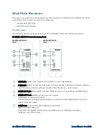
HD-TX-4KZ-211-CHGR and HD-TX-4KZ-421-CHGR Transmitters, Front Panel
①
PWR LED: Lights to indicate that power is being applied to the device. Amber indicates
that the device is booting. Green indicates that the device is operational.
②
AUTO LED and Push Button: Green LED, lights to indicate that automatic switching of
inputs is enabled;
Push button, enables or disables automatic switching of inputs
③
SETUP LED and Push Button: Red LED, lights to indicate that the SETUP push button is
pressed;
Push button, enables Ethernet setup, applicable only when the device is used with a
DMPS Lite switcher
④
INPUT 1 or 1-2 LEDs and Push Buttons: LEDs, green indicates that the corresponding
HDMI input is routed to the output, and amber indicates that a source is detected but is
not routed to the output;
Push buttons, enable manual selection of HDMI input
⑤
INPUT 3 or 3-4 LEDs and Push Buttons: LEDs, green indicates that the corresponding
USB-C DisplayPort input is routed to the output, and amber indicates that a source is
detected but is not routed to the output;
Push buttons, enable manual selection of USB-C DisplayPort input


