background image

5925 Heisley Road • Mentor, OH 44060-1833

Holding Cabinet

FL-2361

Rev. 4 (10/13)

Page 6 of 12

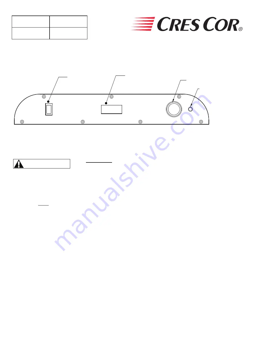
RESET LIGHT

BATTERY INDICATOR

TEMPERATURE

CONTROL

"ON-OFF" SWITCH

CONTROL PANEL

Figure 1: CONTROL PANEL

WARNING

Air is 

VERY HOT


when door is opened.

FIRST TIME START-UP:

1 .  Push the POWER switch to “ELECTRIC”, and 

run the unit for one hour at 200°F.

NOTE:


DO 

NOT

 PUT FOOD INTO CABINET!

This step is to burn off manufacturing oils and excess 

adhesive.

2 .  Let the cabinet cool and wipe inside clean with 

detergent and hot water before first use.

USING ACCESSORY SOLAR PANEL (Optional):

The solar panel is used to increase the time between battery charges when using the cabinet unplugged in gas 

mode . To use the solar system, ensure the solar panel cord is plugged into the solar jack, located in the top right 

corner of the back panel of the unit . Rotate the cabinet and/or tilt the solar panel in order to catch the sunlight . 

The best possible condition for solar charging is when the sunrays hit the panel straight on at 90° angle. 

NOTE:

 It is recommended to keep the solar panel plugged in even when not in use. It will safely maintain the 

battery at full charge for an unlimited amount of time if not placed in a dark area . The solar system is 

not powerful enough to charge the battery from fully drained status in any reasonable amount of time . 

If the battery is fully dead, plug the cabinet in to a grounded 120V outlet to charge .

HOW TO HOLD: 

1 .  Push POWER switch on to “GAS” or “ELECTRIC” . 
2 .  Push the “SET” button on the TEMPERATURE 

CONTROL .  The TEMPERATURE DISPLAY will 

show “SP1” (set point 1) .

3 .  Press “SET” again and the current set point temperature 

will be displayed .

4 .  Press the  

 

 ADJUST buttons to adjust to the 

desired temperature .

5 . 

Press “SET” to save the temperature setting.

6 .  Preheat cabinet for 45 minutes .
7 .  Put product into cabinet .

NOTE:

 Proper food holding temperature is 

140°F/60°C or higher.

HOW TO HOLD FOOD:

OPERATING INSTRUCTIONS

Summary of Contents for HC-UA-11

Page 1: ...Fax Keep this manual for future reference OPERATING and MAINTENANCE INSTRUCTIONS Models HC UA 11 Tri Powered Series Hot Cabinets HC UA 11 WARNING IMPROPER INSTALLATION SERVICE ADJUSTMENTS ALTERATIONS...

Page 2: ...hooting Guide 8 Illustration Cabinet assembly replacement parts 9 Illustration Control panel assembly 10 Illustration Burner assembly 11 Wiring Diagram 12 SERVICE POLICY and AGENCY LIST FL 1400 TABLE...

Page 3: ...Burning Appliances and Equipment CAN CSA B149 1 10 and or local codes 4 The area around cabinet must be kept free and clear from combustible materials 5 DO NOT obstruct the flow of combustion and ven...

Page 4: ...sition b Uncap the cylinder hold upright and insert it in the right rear compartment of the cabinet Hand screw and tighten the cylinder to the gas regulator DO NOT over tighten Check for leaks at the...

Page 5: ...nd then check sight glass below the door to see the burner flames Repeat as necessary Call Service if alarm goes off repeatedly without ignition DO NOT ATTEMPT TO LIGHT BY HAND This cabinet has an aut...

Page 6: ...the solar panel in order to catch the sunlight The best possible condition for solar charging is when the sunrays hit the panel straight on at 90 angle NOTE It is recommended to keep the solar panel p...

Page 7: ...id drips and splashes HOW TO CLEAN THE UNIT Soil Cleaner Method OUTER CABINET Powder Coat WEEKLY OR AS NEEDED Mild detergent and warm water 1 Wipe with clean soft cloth 2 Rinse well 3 Dry gently CABIN...

Page 8: ...it is not on 5b Thermostat is set too low 5c Propane gas tank has expired 5d A gust of wind may have blown out the flame or prevented ignition of the gas 5e Defective electrical components NOTE The co...

Page 9: ...6 Casters w Brake 0569 281 BK 7 Wire Angles 2 per kit 0621 352 K 8 Posts 0696 169 9 Sight Glass 0574 167 18 Cord Set 0810 149 19 High Limit 400 F 0848 033 20 High Limit 0848 060 21 Flanged Inlet 0713...

Page 10: ...on nameplate when ordering parts Control Panel Assembly ITEM DESCRIPTION 120V 10 Power Switch 0808 126 11 Temperature Control 0848 075 CC 12 Battery Indicator 7037 004 13 Reset Light 0766 100 14 Timer...

Page 11: ...7037 005 30 Burner Assembly Complete 8100 001 31 Control Module 8100 001 32 Regulator Solar 7037 002 33 Gas Burner 8100 002 34 Igniter 8100 005 35 Gas Valve 8100 008 36 Regulator 8100 009 37 Pressure...

Page 12: ...MIT 300 F REAR PANEL PWR CORD 3 1 2 4 5 6 7 8 9 10 11 12 13 14 15 16 17 18 19 20 21 22 23 31 30 29 28 27 26 25 24 24 25 26 27 28 29 30 31 38 37 36 34 33 32 39 40 32 33 34 35 36 37 38 39 40 41 42 43 44...

Reviews: