background image

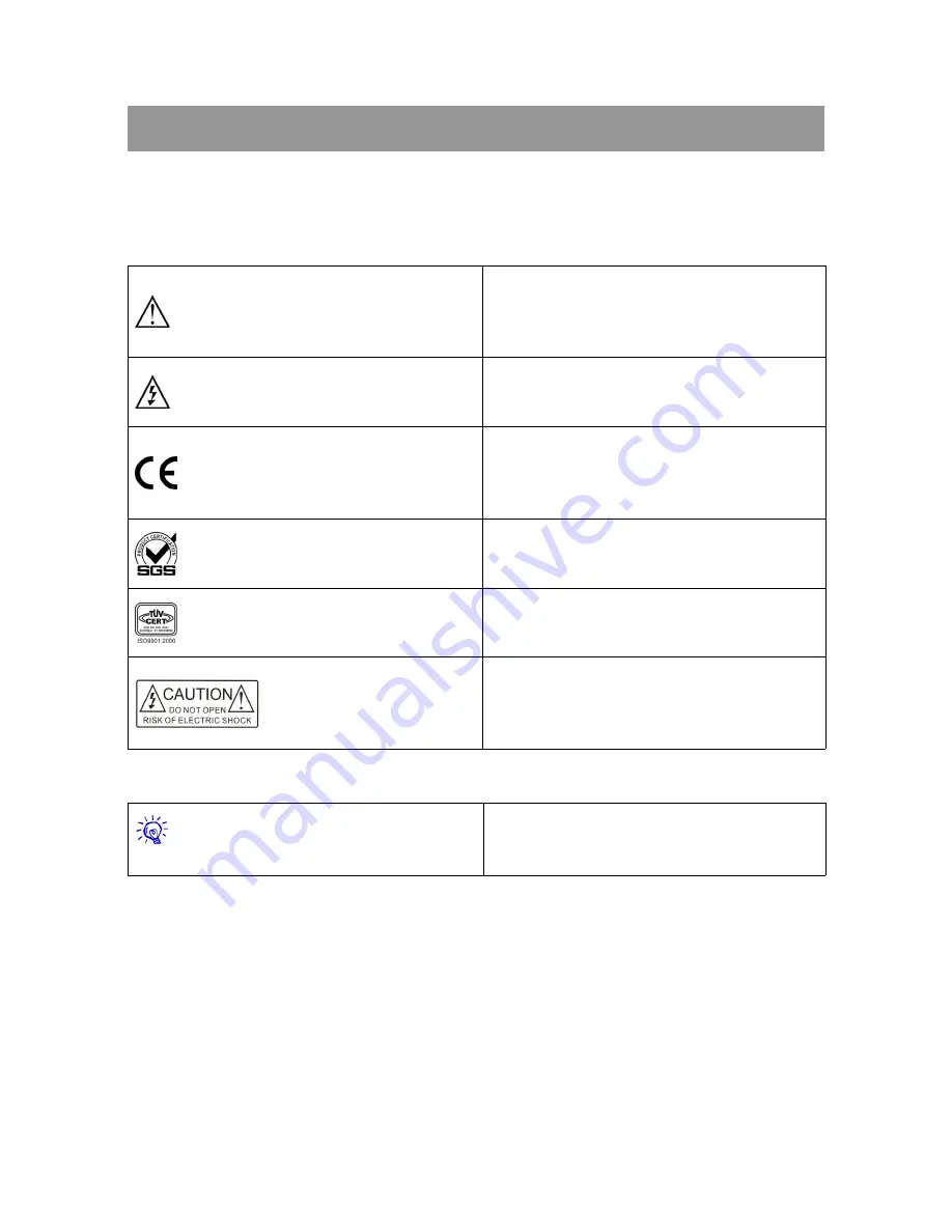
The meaning of symbols

Safety instructions

For your safe and correct use of equipments, we use a lot of symbols on the equipments and in the
manuals, demonstrating the risk of body hurt or possible damage to property for the user or others.
Indications and their meanings are as follow. Please make sure to correctly understand these
instructions before reading the manual.

This is A level product, which may cause radio
interference in the living environment. In this
case, users may need to take the feasible
measures to get around the interference.
Remind users that the dangerous voltage
without

insulation

occurring

within

the

equipment may cause people suffer from shock
CE certification means that the product has
reached the directive safety requirements
defined by the European Union. Users can be
assured about the use of it
SGS certification means that the product has
reached

the

quality

inspection

standards

proposed by the world's largest SGS.
This product passed the ISO9001 international
quality certification (certification body: TUV
Rheinland, Germany).
Warning: in order to avoid electrical shock, do
not open the machine cover, nor is the useless
part allowed to be placed in the box. Please
contact the qualified service personnel.

General information instructions

It lists the factors leading to the unsuccessful
operation or set and the relevant information to
pay attention to.

Summary of Contents for CR-WiFi WG7pip

Page 1: ...Handheld Handheld Wireless Wireless Programmable Programmable Touch Touch Screen Screen User User s s Manual Manual V2 1 version CREATOR CORPORATION CHINA ...

Page 2: ...t insulation occurring within the equipment may cause people suffer from shock CE certification means that the product has reached the directive safety requirements defined by the European Union Users can be assured about the use of it SGS certification means that the product has reached the quality inspection standards proposed by the world s largest SGS This product passed the ISO9001 internatio...

Page 3: ...ng Only after cutting down all external power source can install wiring operation begin or it may cause electric shock or equipment damage This product grounds by the grounding wires To avoid electric shocks grounding wires and the earth must be linked together Before the connection of input or output terminal please make sure this product is correctly grounded Immediately remove all other things ...

Page 4: ...d parameters may be changed since the date of issue please inquire the supplemental information from CREATOR Electronics or local distributors The copyright of this manual belongs to CREATOR Electronics Without permission no unit or individual shall adopt part or all of its content for commercial use The manual is protected by of the Copyright Law of the Peoples Republic of China and other regulat...

Page 5: ... 5 2 Other Windows System Touch Screen DriverInstallation 3 Chapter 2 Touch Screen 4 2 1 Panel Description 4 2 2 System Settings 5 2 2 1 Main Page 5 2 2 2 PIP Page 6 2 2 3 WiFi 7 2 2 4 Date Time Page 8 2 2 5 Locker Page 8 2 2 6 Ver Info 9 2 3 Download Update Data 9 2 4 The Control Interface Description 11 2 5 System Connection Diagram 13 Chapter 3 Technical Parameters 14 Chapter 4 FAQS and Exclusi...

Page 6: ... you to achieve a screen in hand all easy to control 1 1 Features Characteristics Support wireless transmitting distance up to 100M in open air without barrier Support for true color TFT LCD clear high resolution color display CR WiFi WG7pip support 800X480 resolution clear 16 9 widescreen color display CR WiFi WG8pip clear supports for 1024 x 600 resolution and 17 10 widescreen color display Oper...

Page 7: ... non essential when touch screen has enough power USB data line Touch screen driver driver files are stored in TP_ Driver Folder as shown in Figure 1 1 Figure 1 1 2 Store the folder in PC machine installed PC software ThinkDraw C UCB_Drive 3 Start up the touch screen plug USB data cable in a PC then prompt Found New Hardware and pop up Found New Hardware Wizard dialog box shown in Figure 1 2 Figur...

Page 8: ... Next the system begins to install the driver as shown in Figure 1 6 Figure 1 6 6 Click Finish to complete the installation of the touch screen driver then the logo of Creator_g7 devices will appear in Device Manager as shown in Figure 1 7 Figure 1 7 7 Open PC editing software ThinkDraw customized your unique user interface and update to the touch screen to experience 1 5 2 Other Windows System To...

Page 9: ...ve the touch screen at his will as well The power input port support DC 12V 3 3A input The power indicator light when touch screen is in electricity shortage the power indicator light flashes Signal indicator light Signal indicator light flashes when user triggers JNO controls The ON OFF power switch In the case of no external power supply it is used as a power supply switcher Turn to ON it can be...

Page 10: ...n return to the interface in Figure 2 1 Do not want to save the new calibration data wait 30 seconds the system automatically exit calibration interface to return to the Figure 2 1 Interface and maintain the original screen calibration data unchanged For setting the system properties select Setting enter the property setting of system please refer to the 2 2 1 2 2 6 section for details No need to ...

Page 11: ... upper and lower button to achieve Figure 2 5 Figure 2 5 8 In volume option user can drag the slider to adjust the volume of the sound 9 In Backlights option user can drag the slider to adjust the screen brightness 10 Click on the PIP WiFi Date Time About options to enter the respective set interfaces 11 The Default button is used to restore the factory settings for current page 12 If you need to ...

Page 12: ...g the controller 3 If you need to modify the IP information simply click on the corresponding region pop up keyboard and then input the IP address required to modify as shown in figure 2 9 Figure 2 9 click keyboard Enter key to confirm the input and exit the keyboard if do not want to modify click the keyboard Quit to exit 4 Select the corresponding AP hot spots to connect as shown in figure 2 10 ...

Page 13: ...tion on the right side of interface 7 The Refresh button is to refresh the AP information on the left side of interface 8 Click the exit button or Return button in the right upper corner to return to the main setting interface 2 2 4 Date Time Page 1 The Date Time setting interface as shown in figure 2 12 Figure 2 12 2 To modify the time just click on the corresponding position pressing the upper a...

Page 14: ...hen user forgets the lock pattern set up by himself can use the system default lock pattern to unlock as shown in Figure 2 16 yellow dots represent the starting point Figure 2 16 2 2 6 Ver Info Figure 2 17 Shown in Figure 2 17 this page describes the date of manufacture of the touch screen and the system version information Click on the exit button in the right upper corner to return to the main s...

Page 15: ... button as shown in figure 2 22 Note If the USB data lines are not connected properly or touch screen driver is not installed properly when update the data ThinkDraw software will display as shown in figure 2 20 Figure 2 20 Figure 2 21 Figure 2 22 3 PC editing software ThinkDraw and touch screen will display synchronous data transmission schedule as shown in Figure 2 23 figure 2 24 Figure 2 23 Fig...

Page 16: ...ectional control mode when the PGMIII controller feedbacks information When the touch screen is connecting with the controller there will be several different message interfaces as shown in Figure 2 26 2 27 2 28 2 29 Figure 2 26 Figure 2 27 Figure 2 28 Figure 2 29 No indicate AP Please indicate The touch screen informs the user has not specify a AP hotspot then user can enter settings to specify C...

Page 17: ...n trigger JNO controls buttons bars the control state only change after receiving feedback data from controller or else the control state remains 2 When the touch screen is in the RF one way control mode the PGMII PGMIII controller does not feedback information 1 Starting the touch screen will pop up prompt information inform the user that the touch screen in a certain controlled manner The prompt...

Page 18: ...CREATOR CHINA 2013 08 WWW CREATOR1997 COM 13 Handheld Wireless Programmable Touch Screen User s Manual 2 5 System Connection Diagram Mode 1 Mode 2 ...

Page 19: ...n 10 1 resistive touch screen ON OFF Power on off toggle RF WiFi switch Power on off toggle RF WiFi switch Reset Reset button Reset button The indicating lamp Power indicator light white Signal indicator Orange Power indicator light white Signal indicator Orange Power interface DC12V 3 3A input DC12V 3 3A input USB interface Micro USB Micro USB Audio Speaker Two channel stereo L R output 8Ω1W Two ...

Page 20: ...i CR WiFi WG7pip WG7pip CR WiFi CR WiFi WG8pip WG8pip Charging saturation time 5H 5H Charging temperature 0 45 0 45 Specifications Lithium ion rechargeable battery 7 4V Lithium ion rechargeable battery 7 4V Specifications Weight About 0 9 kg About 1 0 kg The graphics engine BITBLIT and rotatory 2D graphics acceleration engine ...

Page 21: ...h screen Make sure the USB data cable is connected properly Check the touch screen driver is successfully installed in this case can re install the driver to resolve Check whether the touch screen user program is the same with touch screen model Check whether the computer USB port can work normally Check whether the touch screen has power and light the touch screen No display on touch screen Batte...

Page 22: ...et places 4 Avoid the use of sharp rough hard object click on the touch screen surface recommend hand or a dedicated touch pen 5 Click on the touch screen with the appropriate intensity not too large force Click to avoid crushing touch screen 6 Touch screen battery is touch screen specific and can not be used for other purposes to avoid damage to the battery 7 The battery has a certain life repeat...

Page 23: ...CREATOR CORPORATION CHINA Copyright by CREATOR Last Revision 08 2013 ...

Reviews: