Creative Cedar Designs Jungle Fun 3201 Owner'S Manual And Assembly Instructions Download Page 6

Helpful Installation Hints 

1. Depending on your experience, assembly of this Play set should take 

approximately 6 to 12 hours after inventory of parts. Therefore, we recommend

you set aside a full day for assembly.

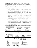
2. Identify all of the parts for your Playcenter.  Empty each box and lay out boards 

so you can see each part.  Your instruction book will have detailed drawings that 

will make it easy for you to recognize individual parts.  Keep all hardware and 

metal parts separate from wooden pieces. 

3. After everything is laid out, check carefully to ensure all parts are present.  Make 

sure there are no broken boards. 

4. Find an area to sort your hardware.  It is best to open the hardware on a solid 

surface so that you do not lose any pieces in the grass.  This will save time and 

familiarize you with all the different pieces in the hardware bag.

5. Important note:  Wood has some natural defects such as knots, surface cracks, 

etc…  We reject parts that are structurally defective.  We use a high quality 

lumber in our structures; however, you should inspect each part for splinters or 

rough spots and sand them smooth to prevent injury. 

6. After steps 1 thru 4 have been completed, read all the way through the 

instructions completely.  Reading instructions after you have studied the parts will 

help you understand more clearly the installation process, and help to eliminate

unnecessary mistakes.

7. Pay close attention to the diameter and length of each bolt and screw.

8. Swing hangers should be buried past the threads, so that the loop is against the 

swing beam. Creative Cedar Designs is not responsible for incorrect installations of 

swing hangers.  Failure to properly install swing hangers may cause severe injury. 

9. Never tighten hardware completely at first.  It helps to have some adjustment for 

bolt alignment while you are attaching parts together.  After everything is square, 

tighten each joint. 

10. After the main unit is assembled it is critical that the floor is level and square.  If 

the main frame is not level, the walls and floor will be out of square. 

11. After you complete installation, make sure every bolt, screw, and nut is tight, and 

every board is secure.  Wood will expand and contract with the seasons.  Check 

all bolt connections and swing hangers every two weeks. 

12. Place the set on level ground, not less than 6ft from any structure or obstruction

such as a fence, garage, house, overhanging branches, laundry lines, or electrical 

wires.

READ! VERY IMPORTANT! 

If you are missing parts or have questions regarding the installation of our quality product PLEASE call us

directly at our offices (1-888-363-4967).  Our trained staff will be happy to assist you.

Customer service hours: 

Monday thru Friday 9am to 4pm 

 Eastern Standard Time.

E-mail: [email protected]


4

Summary of Contents for Jungle Fun 3201

Page 1: ...Model 3201 Jungle Fun SGS COC 005310 1996 Forest Stewardship Council A C For FSC certified products look for the FSC label Follow the Sequoia plans thru phase 23 then proceed with these instructions...

Page 2: ...sitioning Your Playcenter 3 Tools Required for Assembly 3 Helpful Installation Hints 4 Suggested Playground Surfacing 5 Operating Instructions 6 Maintenance Instructions 7 Disposal Instructions 7 CPSC...

Page 3: ...HELP WITH WHAT YOU NEED For more efficient service please log onto our website at www creativecedardesigns com and fill out a request for missing or damaged parts A completed product registration is...

Page 4: ...n your installation continued satisfaction and safe operation of your Creative Cedar Designs purchase Always keep the safety of your children in mind as your play structure is being built and as your...

Page 5: ...idea to place your Playcenter in an area that is convenient for adults to watch children at play 6 Create a site free of obstacles that could cause injuries such as low overhanging tree branches over...

Page 6: ...you understand more clearly the installation process and help to eliminate unnecessary mistakes 7 Pay close attention to the diameter and length of each bolt and screw 8 Swing hangers should be burie...

Page 7: ...Standard Specification of Impact Attenuation of Surfacing Materials within the Use Zone of Playground Equipment The following chart explains the fall height in feet from which a life threatening head...

Page 8: ...to sit in the center of the swings with their full weight on the seats 9 Instruct children not to use the equipment in a manner other than intended 10 Instruct children to always go down slides feet f...

Page 9: ...parts 6 For rusted areas on metallic members such as monkey bars hand supports brackets etc sand and repaint using a non lead based paint meeting the requirements of Title 16 CRF Part 1303 7 Inspect w...

Page 10: ...ecause children may deliberately jump from a moving swing the shock absorbing material should extend in the front and rear of a swing a minimum distance of 2 times the height of the pivot point measur...

Page 11: ...may present a choking hazard to small children Please keep these bags and all plastic bags out of the reach of children Do no allow children to play with them and dispose of them immediately when emp...

Page 12: ...h phase thoroughly The written steps may include important information not shown in the illustrations 4 Pay close attention to the Items needed and Hardware needed sections of each phase They can be a...

Page 13: ...RIDGE H PF3819 1 1 X 5 X 25 BRIDGE I PF3818 1 1 X 5 X 24 1 2 BRIDGE J PF3817 1 1 X 5 X 24 BRIDGE K PF3816 6 1 X 3 5 8 X 24 STEPS PF3815 2 1 X 3 1 2 X 49 3 8 BASE LONG PF3808 2 1 X 3 1 2 X 27 STEP FRON...

Page 14: ...Accessories 26 BRIDGE SPACERS P301 4 FENCE STAPLE H 8 CABLE CLAMP O2 1 BRIDGE CABLE O1 1 BRIDGE SUPPORT STRAP M301 2 ROPE RAILING Q 12 Parts Identification Wooden Bridge g 4 GREEN L BRACKET M002...

Page 15: ...oc Nut 5 16LN 5 16 x 1 1 2 Lag Bolt L 8 1 Do not include bolt head when measuring length of bolt NOTES 2 Include full length of deck screw when measuring 1 4 1 1 2 3 4 2 3 4 5 6 It is very important t...

Page 16: ...T 1 x 3 1 2 x 49 3 8 BASE LONG 1 x 3 5 8 x 24 STEPS 1 x 5 x 24 BRIDGE K 1 x 5 x 24 1 2 BRIDGE J 1 x 5 x 25 BRIDGE I 1 x 5 x 25 1 2 BRIDGE H 1 x 5 x 26 BRIDGE G 1 x 5 x 26 1 2 BRIDGE F 1 x 5 x 27 BRIDG...

Page 17: ...hase 25 SLIDE ATTACHMENT 15 POSITION SLIDE CENTERED IN AN OPENING AND 4 INTO THE TOWER AS SHOWN INSTALL 4 TRUSS SCREWS PER SLIDE LARGE WAVE SLIDE GREEN Phase Parts Phase Hardware 1 Truss Head Screw S...

Page 18: ...shown in STEP 1 2 Attach Step Support boards as shown in STEP 2 3 Attach Bridge Platform Step boards as shown in STEP 3 4 Attach Step Support boards as shown in STEP 4 PF3830 8 3 8 PF3805 PF3837 PF38...

Page 19: ...pe Railing Support boards as shown in STEP 2 3 Attach Bridge Cable Support board as shown in STEP 3 4 Attach Bridge Platform Angle Support boards as shown in STEP 4 20 COUNTER BORE S FACING THIS SIDE...

Page 20: ...BRIDGE ASSEMBLY STEP 2 STEP 1 63 1 2 GAP PF 3829 8 2 1 2 DECK SCREWS Rope Railing Support must be plumb and level Assemble Bridge Platform cont HOLE DETAIL 1 Attach Top Step boards as shown in STEP 1...

Page 21: ...Z3259 BRIDGE SUPPORT WZ3259 BRIDGE SUPPORT LD203 UPRIGHT LD203 UPRIGHT LM226 WALL RAIL LM219 END FLOOR SUPPORT 2 3 1 2 LAG SCREWS BOTH SIDES 2 5 16 FLAT WASHERS STEP 1 1 MARK TWO HOLES ON UPRIGHTS AS...

Page 22: ...p 2 Mark and drill 4 5 16 holes thru upgrights 2 on each upright Step 3 Insert 4 5 16 T nuts into backside of uprights Step 4 Attach M301 Support Strap with 4 1 1 4 deck screws 4 5 16 X 3 1 4 Hex bolt...

Page 23: ...1 Phase 31 BRIDGE ASSEMBLY 5 16 x 6 DRILL BIT LD203 UPRIGHT 65 1 16 80 1 16 Bridge Tower Prep Rope Railing Step 1 Mark hole locations centered on uprights as shown Step 2 Drill 5 16 holes at locations...

Page 24: ...Eye bolt thru platform upright and secure with hardware as shown 3 Repeat steps for opposite side NOTE Space between upright and first rope Phase Hardware Phase Hardware K1 8 5 16 Flat Washer G1 8 5...

Page 25: ...ope Railing as shown below The cable will be routed starting from the left Tower side through the Bridge Boards Platform sturcture then back through the Bridge Boards as indicated by the arrows 1 1 X...

Page 26: ...le through left side of Bridge Boards as described in previous page Step 2 Thread cable through Platform down through the top across to the opposite side Step 3 Route cable through right side of Bridg...

Page 27: ...IDGE CLEAT PF3783 H 2 Fence Staple STEP 1 STEP 2 2 1 4 4 1 4 Assemble Bridge Secure Cable and Attach Cleats 1 Secure cable running underneath the Bridge Platform as shown in STEP 1 2 Attach Cleats as...

Page 28: ...rs STEP 1 Assemble Bridge Secure Cable and Attach tower 1 Thread Bridge Cable thru M301 Bracket WZ3259 Support as shown in STEP1 NOTE Deck boards are removed for clarity Bridge Spacers LD203 Bridge Ca...

Page 29: ...t and install Cable Clamp tight to WZ3259 Support 2 Install a fence staple above the Cable Clamp into WZ3259 Support for each cable as shown in STEP 1 3 Drill 3 8 hole s at location shown on uprights...

Page 30: ...CAP 5 16 LOCK NUT 5 16 FLAT WASHER EYE BOLT ASSEMBLY UNDER DECK VIEW LD203 TOP VIEW LM211 LM210 WZ3259 BRIDGE SUPPORT LM219 Assemble Bridge Finish and Secure Bridge 1 Thread cable through Eye Bolt and...

Page 31: ...ry board is secure Make sure playset is level SECURE PLAYSET 1 Place anchors at the locations shown 2 Twist the anchors into the ground until only the loop is exposed as shown 3 Place the metal strap...

Page 32: ...damaged by acts of God negligence misuse or accident or which have been modified or repaired by unauthorized persons b the cost of labor c the cost of shipping the product any part or any replacement...

Page 33: ...scription of the warranty issue 3 Photos of warranted parts and of the entire play system If any of the above steps are not completed there may be delays in the completion of your claim or possibly wa...

Page 34: ..._______________ City State Zip Code ___________________________________________________ Phone ________________________________________________________________ Date of Purchase ________________________...

Page 35: ...stration Card along with a copy of the receipt and return to Creative Cedar Designs within 30 days of original purchase in order to validate time of purchase for warranty FOLD HERE Place Stamp Here Cr...

Reviews: